Optical disk recording and/or reproducing apparatus

a technology of optical disk and recording device, which is applied in the field of optical disk recording and/or reproducing apparatus, can solve the problems of unstable rotation of the optical disk, unduly complex structure of the disk clamper, and inability to vibrate the elastic device, etc., and achieves the effect of preventing misreading by the optical pick-up head and simple structur

Inactive Publication Date: 2007-05-29
HON HAI PRECISION IND CO LTD
View PDF7 Cites 4 Cited by
  • Summary
  • Abstract
  • Description
  • Claims
  • Application Information

AI Technical Summary

Benefits of technology

[0008]Accordingly, an object of the present invention is to provide an optical disk recording and / or reproducing apparatus which has a relatively simple structure and which can effectively prevent misreading by an optical pick-up head.

Problems solved by technology

However, this kind of disk clamper has an unduly complex structure.
In addition, if the optical disk recording and / or reproducing apparatus is subjected to vibration from an outside source, the first elastic device and the second elastic device are liable to vibrate too, and the rotation of the optical disk may become unstable.
Furthermore, because the diameter of the disk clamper is usually small, and because the second elastic device is usually smaller than the disk clamper, the second elastic device cannot provide enough clamping force to reliably clamp the optical disk.
Moreover, when an optical disk is rotating in the optical disk recording and / or reproducing apparatus, the peripheral portion of the disk clamper is liable to scrape and damage the data storage area of the optical disk.

Method used


Image

  • Optical disk recording and/or reproducing apparatus
  • Optical disk recording and/or reproducing apparatus
  • Optical disk recording and/or reproducing apparatus

Examples


Embodiment Construction

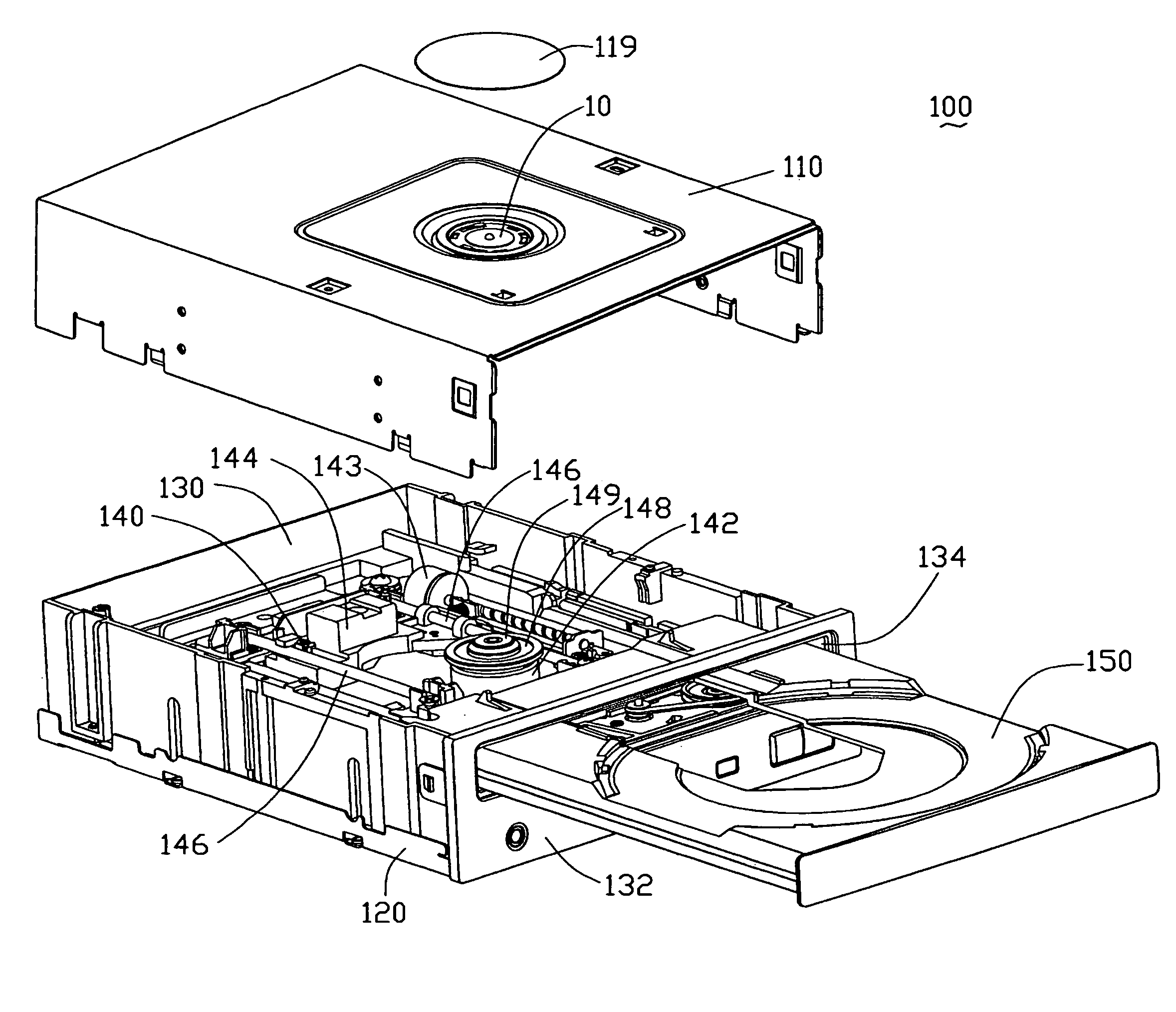
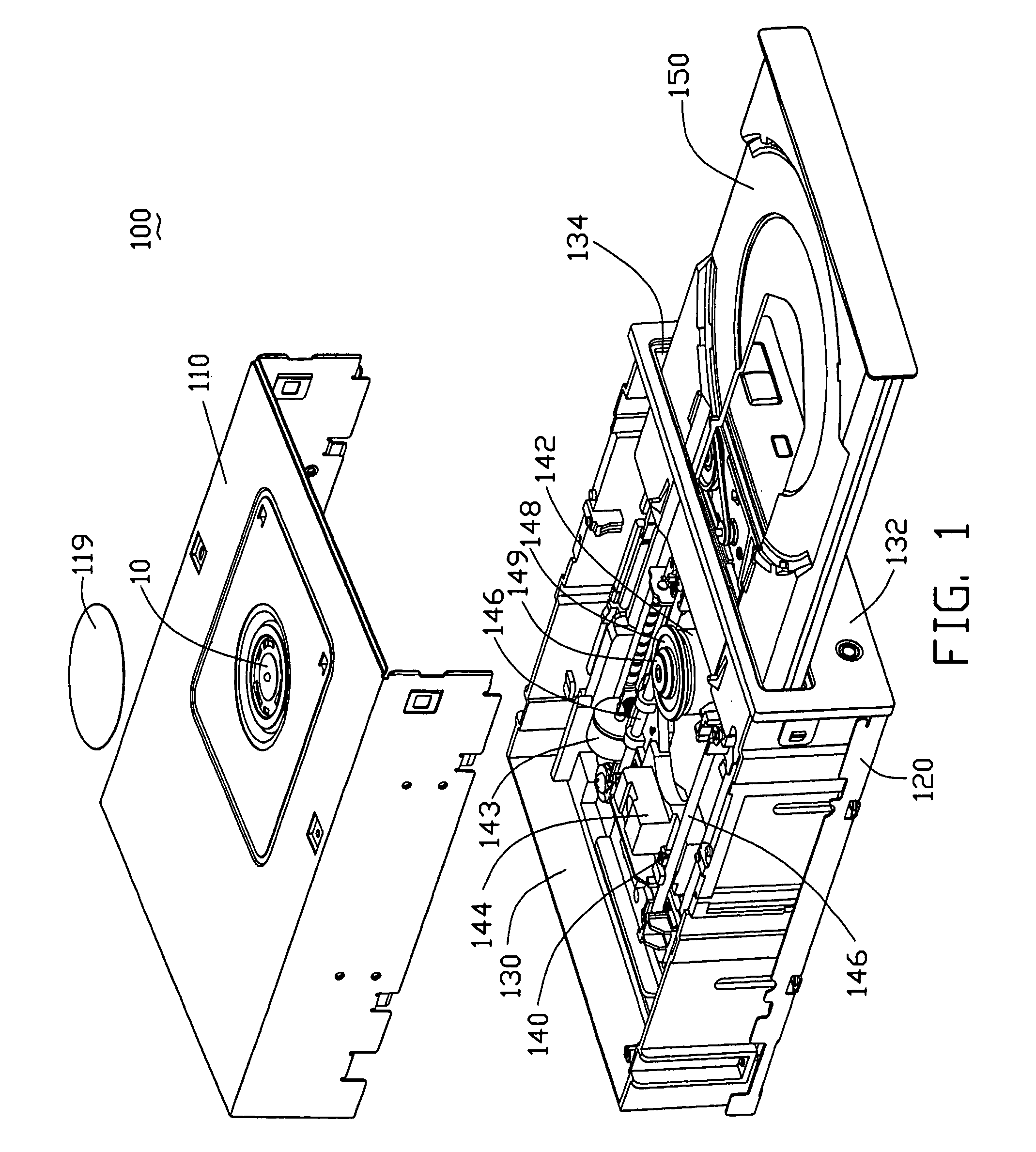
[0016]Referring to FIG. 1, an optical disk recording and / or reproducing apparatus 100 in accordance with the present invention may be a DVD-ROM (Digital Video Disk-Read Only Memory) or CD-ROM (Compact Disk-Read Only Memory) drive. The optical disk recording and / or reproducing apparatus 100 includes a first case 110, a second case 120, a base 130, a main body 140, and a disk tray 150. A disk clamper 10 is positioned on the first case 110. The base 130 has a front panel 132, with an opening 134 defined therein. The disk tray 150 is positioned on the base 130, and moves backward and forward (horizontally) with respect to the main body 140 for conveying an optical disk 220 (see FIG. 5) through the opening 134. The main body 140 is accommodated in the base 130, and includes a spindle motor 142, a stepping motor 143, an optical pick-up head 144, two guiding frames 146 and a turntable 148. The optical pick-up head 144 is hung between the guiding frames 146. The optical pick-up head 144 mov...


PUM

PropertyMeasurementUnit
diameteraaaaaaaaaa
clamping areaaaaaaaaaaa
elasticaaaaaaaaaa

Abstract

An optical disk recording and / or reproducing apparatus (100) includes a first case (110), a base (130), and a main body (140). The first case includes a supporting device (116) with a hole (118) defined therein, and a disk clamper (10). The main body is accommodated in the base, and includes a spindle motor (142) and a turntable (148). A magnetic element (149) is positioned on the turntable. The disk clamper includes a clamping body (12), a magnet (14), and a clip (16). The clamping body and the clip are respectively positioned on lower and upper sides of the supporting device, and fixed together through the hole. The magnet is sandwiched between the clamping body and the clip. In use, because of attraction of the magnet and the magnetic element, opposite sides of an optical disk (220) are respectively clamped by the clamping body and the turntable.

Description

BACKGROUND OF THE INVENTION[0001]1. Field of the Invention[0002]The present invention generally relates to an optical disk recording and / or reproducing apparatus which has a relatively simple structure and which can firmly clamp an optical disk therein.[0003]2. Description of Prior Art[0004]A typical optical disk defines a clamping area between a central hole thereof and a data storage area thereof. The clamping area is used for a disk clamper of an optical disk recording and / or reproducing apparatus to clamp the optical disk. In operation, the optical disk is carried into or out from the optical disk recording and / or reproducing apparatus by a sliding loading device. When the optical disk is loaded, it is positioned on a turntable of the optical disk recording and / or reproducing apparatus. The turntable rotates the optical disk, and an optical pick-up head is driven along a radial direction of the optical disk by a driving mechanism and a guiding mechanism. The optical pick-up head...

Claims


Application Information

Patent Timeline
Patent Type & Authority Patents(United States)
IPC IPC(8): G11B33/02G11B17/028G11B17/04
CPCG11B17/0285G11B17/056
Inventor PAN, GUO-CHEN
Owner HON HAI PRECISION IND CO LTD
Why Eureka
Try Eureka