
Winch assembly for a lift structure supportive of a recreational boat and related watercraft

a technology for recreational boats and watercraft, which is applied in the direction of special-purpose vessels, transportation and packaging, hoisting equipment, etc., can solve the problems of slow manual lifting of boats, damage or make the interior of boats uncomfortable for use, and even dangerous, so as to reduce the exposure to moving parts, easy operation, and reliable

Inactive Publication Date: 2007-06-05
LEDFORD MICHAEL PAUL
View PDF13 Cites 31 Cited by
  • Summary
  • Abstract
  • Description
  • Claims
  • Application Information

AI Technical Summary

Benefits of technology

Enables efficient and safe lifting and lowering of boats by a single user, reducing exposure to moving parts and protecting the boat from damage, while allowing for quick response to weather changes and facilitating maintenance.

Problems solved by technology

Sun fading, bird droppings and rain can all damage or make the interior of the boat uncomfortable for use.
Since storms can and do approach suddenly, the manual process of lifting a boat can be slow and even dangerous in the face of a fast approaching storm.

Method used


Image

  • Winch assembly for a lift structure supportive of a recreational boat and related watercraft
  • Winch assembly for a lift structure supportive of a recreational boat and related watercraft
  • Winch assembly for a lift structure supportive of a recreational boat and related watercraft

Examples


Embodiment Construction

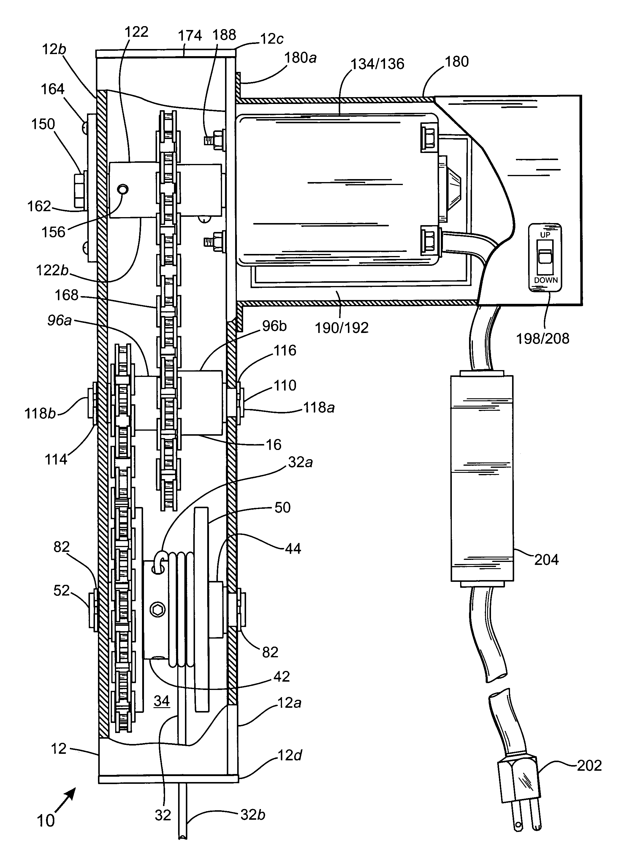
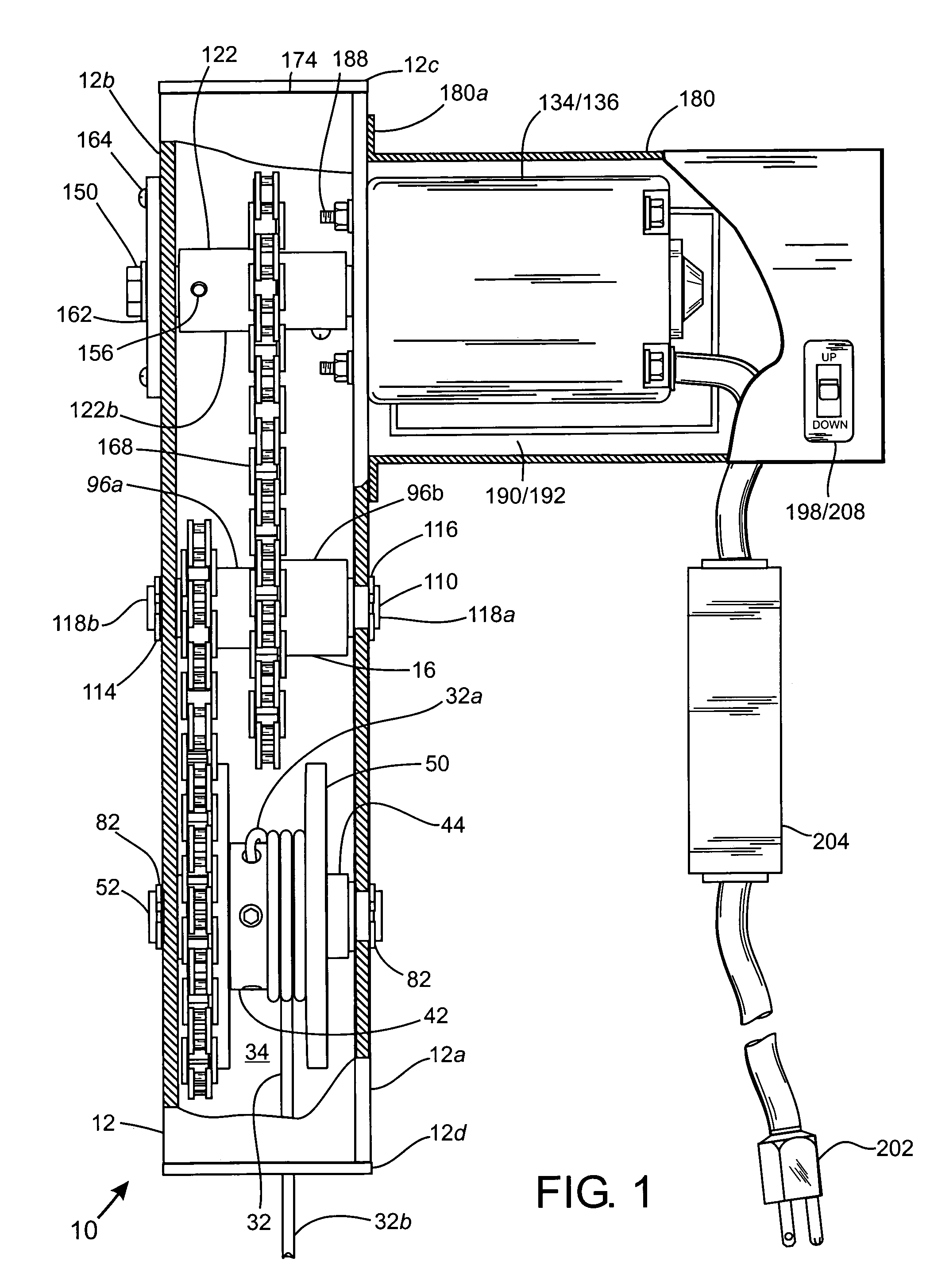
[0043]While this invention is susceptible of being embodied in many different forms, the preferred embodiment of the invention is illustrated in the accompanying drawings and described in detail hereinafter with the understanding that the present disclosure is to be considered to exemplify the principles of the present invention and is not intended to limit the invention to the embodiments illustrated and presented herein. The present invention has particular utility as a device for use with new and existing boat lift structures, particularly serving as automated means for lowering and lifting a recreational boat to and from the water's surface by a single operator.

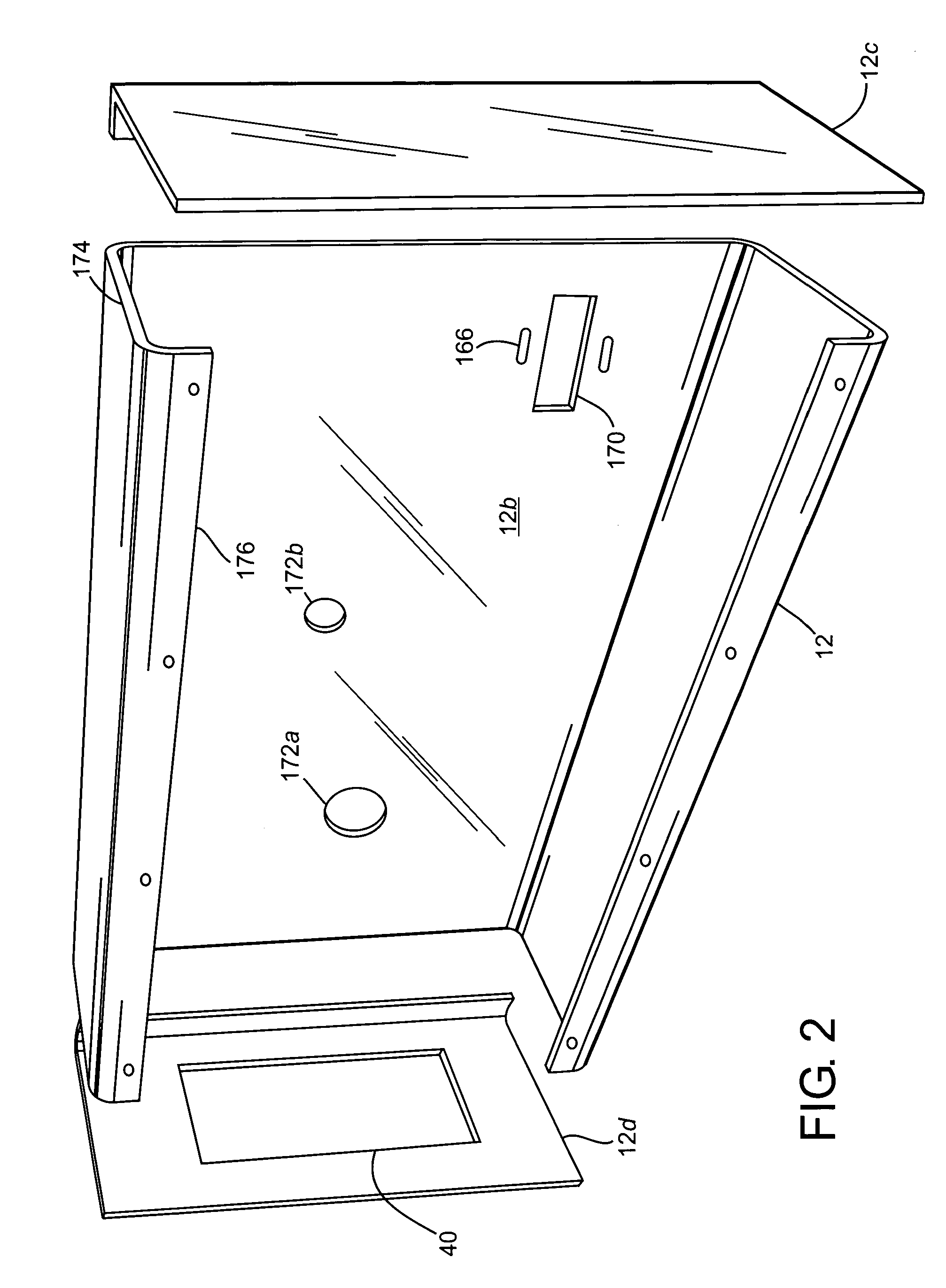
[0044]Referring now to FIGS. 1 and 2, there is shown generally at 10 a winch assembly comprising a chassis 12 having front access and back mount plates 12a, 12b and top and bottom sides 12c, 12d collectively configured to mount and house therein three drive assemblies 14, 16, 18 each having one or more plate sprockets fix...


PUM


Abstract

An improved winch assembly adaptably configured for use with a new or existing lift structure suitably dedicated for short- and long-term storage of a recreational boat and related watercraft. The winch assembly comprises three drive assemblies housed and mounted within a chassis. The first drive assembly comprises a first plate sprocket and a pair of cable guards collectively mounted onto a cable hub to form a spool assembly for accepting and winding thereon a predetermined length of cabling. The second drive assembly comprises a stepped hub having three discrete cylindrical surfaces to form first and second annular walls for mounting thereagainst primary and secondary plate sprockets and an inner bore extending therethrough for receiving therein an intermediate axle having ends affixed to the chassis, wherein the primary plate sprocket is connectively coupled with the first plate sprocket by a drive chain. The third drive assembly comprises a motor hub mounted to the chassis by means of a mount plate and having primary and secondary cylindrical surfaces each of differing diameter to form an annular wall for mounting thereagainst a plate sprocket connectively coupled to the secondary plate sprocket by a motor drive chain and first and second elongate bores extending longitudinally through the primary and secondary cylindrical surfaces for receiving and housing therein an output shaft of either a 110 / 220- or 12 / 24-volt electric motor and an axle having a hex-shaped head positioned externally to the mount plate for manual turning of the drive assemblies in the event of the electric motor's failure, respectively.

Description

CROSS-REFERENCE TO RELATED APPLICATIONS[0001]This application claims the benefit of priority from U.S. Provisional Application Ser. No. 60 / 615,454 filed Oct. 2, 2004, entitled “Improved Winch Assembly for a Lift Structure Supportive of a Recreational Boat and Related Watercraft,” the disclosures of which, including all attached documents, are incorporated herein by reference in their entirety for all purposes.FIELD OF THE INVENTION[0002]The present invention relates to an improved winch assembly adaptably configured for use with new and existing lift structures suitably dedicated for short- and long-term storage of a recreational boat and related watercraft. More particularly, the present invention relates to an improved winch assembly comprising automated means for lowering and raising the recreational boat to and from the water's surface insofar to facilitate the docking and undocking of the boat by a single user.BACKGROUND OF THE INVENTION[0003]The prior art describes a variety o...

Claims


Application Information

Patent Timeline
Patent Type & Authority Patents(United States)
IPC IPC(8): B66D1/22
CPCB66D1/14B66F7/02
Inventor LEDFORD, MICHAEL PAUL
Owner LEDFORD MICHAEL PAUL
Learn More