Hydraulic vehicle seat adjustment with system protection valve

a technology of vehicle seat and protection valve, which is applied in the direction of movable seats, roofs, pedestrian/occupant safety arrangements, etc., can solve the problems of increasing the cost and weight of the vehicle seat, jerky movement and adjustment, and noisy electric motors and associated gearing, etc., and achieves high pressure

Inactive Publication Date: 2007-06-05
LEAR CORP
View PDF29 Cites 10 Cited by
  • Summary
  • Abstract
  • Description
  • Claims
  • Application Information

AI Technical Summary

Benefits of technology

[0017]Such a biassing spring arrangement allows the closure portion to return to the first position, a

Problems solved by technology

Whilst such electrically powered adjustable seats are commonplace, the electric motors and associated gearing can often be relatively and undesirably noisy as well as providing often jerky movement and adjustment.
This increases costs and weight of the vehicle seat and furthermore the additional motors and gearing take up increasing space within the seat assembly.
In spite of these, and other, advantages of hydraulically powered seat adjustments they have not been adopted for widespread automotive vehicle seat use over the considerable number of years since they have initially been proposed.
Overall, and although hydraulics are used in other areas in automotive vehicles (

Method used


Image

  • Hydraulic vehicle seat adjustment with system protection valve
  • Hydraulic vehicle seat adjustment with system protection valve
  • Hydraulic vehicle seat adjustment with system protection valve

Examples


Embodiment Construction

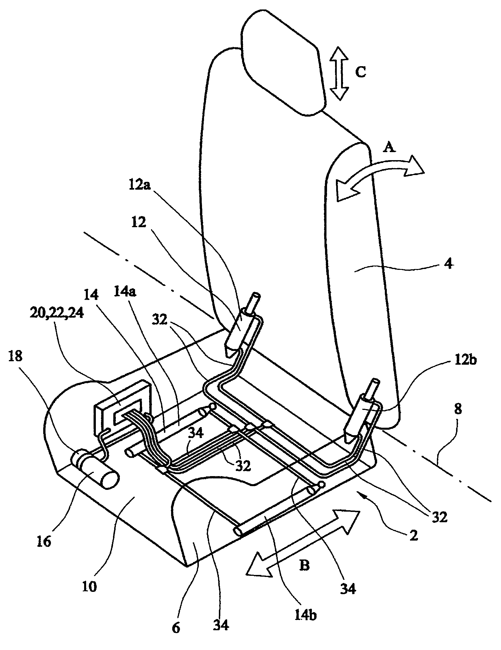
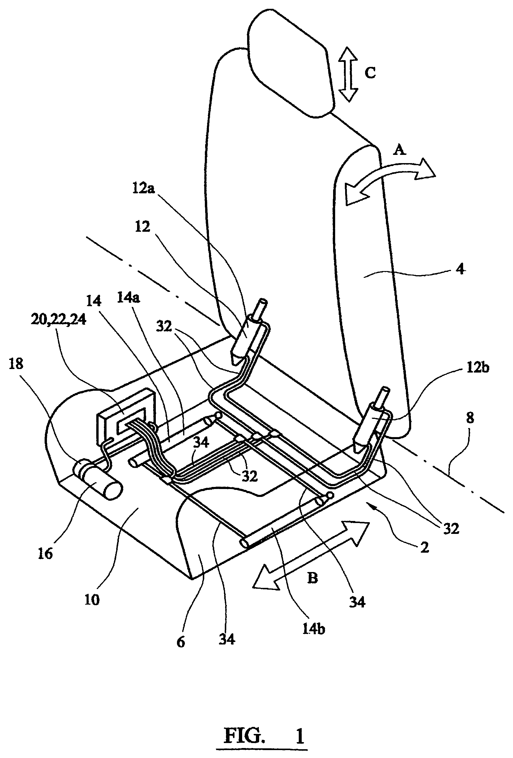
[0029]Referring to FIG. 1 there is shown a schematic illustration of the disposition of a hydraulically powered seat adjustment system 10 within an outline of an automotive vehicle seat 2. The vehicle seat 2 includes a seat back 4 which is pivotally connected to a bottom seat cushion 6, in a conventional manner, at one end about a horizontal lateral axis 8 such that the angle of the seat back 4 can be adjusted relative to the generally horizontally disposed seat bottom cushion 6 as indicated by arrow A. The seat bottom cushion 6 is slidably mounted to the vehicle floor (not shown) in a conventional manner, for example using a pair of sliding seat tracks or rail assemblies (not shown), to allow the seat cushion 6 and seat 2 to be slid fore and aft as indicated by arrow B. The fore and aft position of the seat 2, and angle of the seat back 4, are adjusted and secured in position by a powered hydraulic adjustment system 10 operated by a seat occupant.

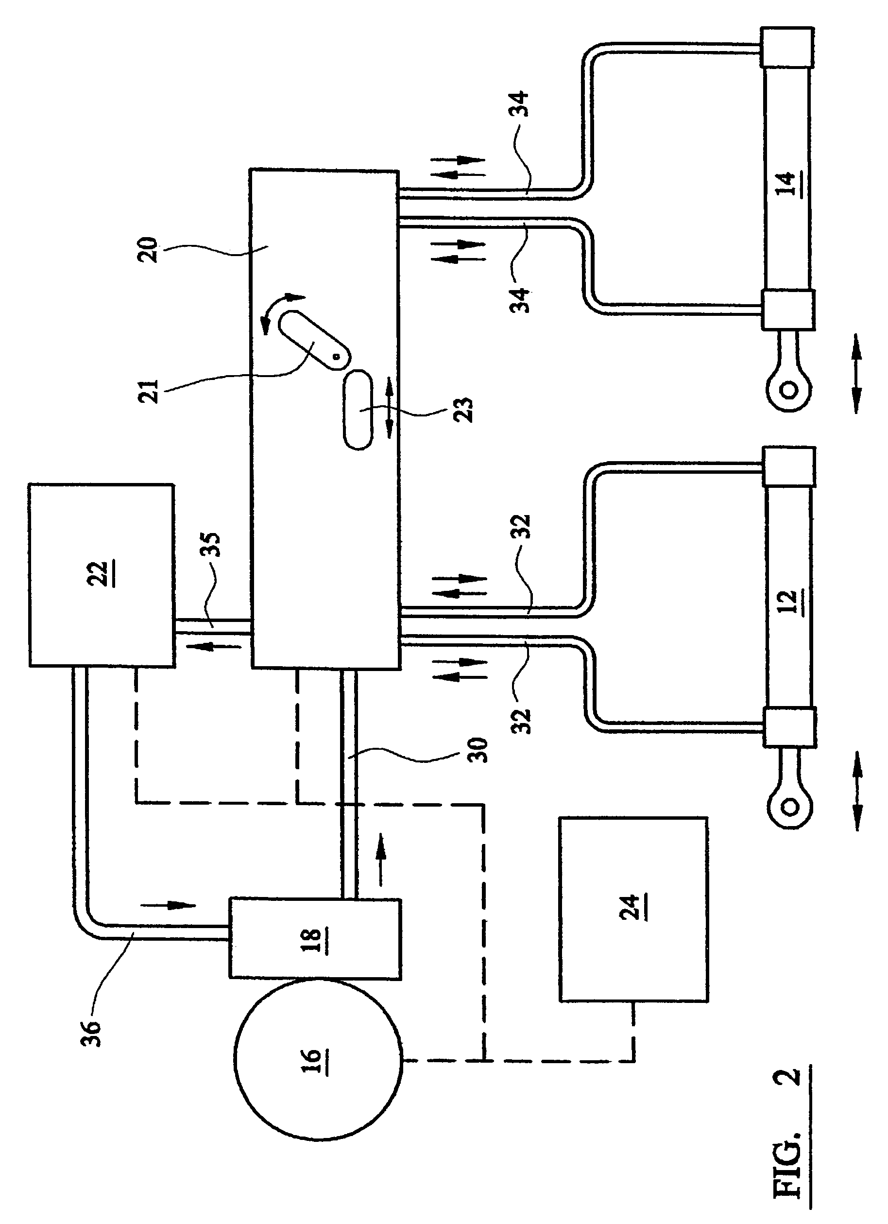
[0030]The hydraulic adjustment syst...


PUM


Abstract

A hydraulic vehicle seat system providing powered adjustment of the position of a seat or seat portion. The system comprises a pump, flow controller, and hydraulic actuator arranged in a hydraulic circuit. The actuator includes a first and second system protection valves for the respective inlet and outlet of the actuator. The system protection valves are adapted to be activated in response to pressure within the actuator exceeding a predetermined threshold level. When activated the system protection valves close off the respective inlet and outlets to hydraulically isolate the actuator and hydraulic fluid within the actuator from the remainder of the hydraulic circuit and adjustment system. This protects the remainder of the circuit and system from excessive pressures which may be generated within an by the actuators under crash loading.

Description

CROSS REFERENCE TO RELATED APPLICATIONS[0001]This application claims priority to Great Britain Patent Application No. 0324558.6 filed Oct. 22, 2003, the disclosures of which are incorporated herein by reference.BACKGROUND OF THE INVENTION[0002]The present invention relates to a vehicle seats, in particular to hydraulically or fluid powered adjustable automotive vehicle seats.[0003]In order to comfortably accommodate various sizes and shapes of occupants vehicle seats are generally provided with various adjustment mechanisms to adjust the position of the seat within the vehicle and / or move various movable portions of the seat. Typically vehicle seats are provided with fore and aft adjustment, and the seat back is pivotally mounted to a seat bottom cushion such that the angle of the seat back to the bottom cushion of the seat can be adjusted. Other adjustment and adjustment mechanisms may also be provided to for example adjust the height of the vehicle seat, angle and tilt of the seat...

Claims


Application Information

Patent Timeline
IPC IPC(8): B60N2/02B60N2/06B60N2/23B60N2/433B60N2/90
CPCB60N2/0224B60N2/067B60N2/231B60N2/43B60N2/4415B60N2/914
Inventor CHRISTOPHER, HUGH H.
Owner LEAR CORP
Why Eureka
Try Eureka