Seat gantry

a seat gantry and passenger seat technology, applied in the field of passenger seat handling, can solve the problems of increasing increasing the complexity of passenger transportation seats, and increasing the difficulty of traditional methods of handling and installing seats, so as to reduce the physical requirements of seat handling operators, reduce the traditional crew of operators, and facilitate the handling

Active Publication Date: 2007-06-05
THE BOEING CO
View PDF10 Cites 6 Cited by
  • Summary
  • Abstract
  • Description
  • Claims
  • Application Information

AI Technical Summary

Benefits of technology

[0007]A system and method for handling, installing, and removing passenger transportation seats and seat assemblies and components thereof are therefore provided. A single operator or two operators may easily handle a large and heavy seat assembly using a seat gantry system of the present invention, reducing a traditional crew of operators and reducing the physical requirements of a seat handling operator. The system and components thereof are used to perform or assist in handling of seat assemblies and are designed with features to assist in use with seat assemblies, such as being able to easily negotiate airplane aisles, currently as little as 15 inches wide. The system and components thereof are also designed to easily remove a seat cart from a shipping foundation, transport the seat assembly onto the airplane, and lower the seat assembly into position for installation.
[0008]A seat gantry system and components thereof eliminate the need for any manual lifting of a seat assembly, also referred to in this application generally as a seat, seat unit, or seat group and where a seat assembly, unit, or group may include multiple seats. A hoist attached to a frame of a seat gantry of one embodiment of the present invention provides the upward and downward forces of lifting a seat assembly. This eliminates much of the ergonomic risk associated with manual handling, transporting, and installing of seat assemblies as well as the potential for physical damage to the seat assemblies and vehicle interior.
[0011]An inside seat gantry may be used for lifting a seat assembly from a seat cart and positioning and lowering the seat assembly for installation once the seat cart has been removed. An inside seat gantry is advantageously included in part due to the problems and difficulties of lifting a seat or seat assembly from a seat cart and the problems and difficulties of properly positioning, lowering, and installing a seat or seat assembly into a vehicle floor. To remove a seat assembly from a seat cart, the seat assembly must be lifted high enough to clear the seat cart from below the seat assembly. A properly designed inside seat gantry may be used in place of a separate outside seat gantry; features beneficial for use of an inside seat gantry in place of an outside seat gantry include the ability to increase the overall height for greater freedom of operation involving various heights of shipping foundations and an increased wheel base for greater stability, allowing for safe movement of a seat assembly while suspended from such a seat gantry.
[0012]A seat gantry system or method may also include an artificial lifting torso for use with an outside seat gantry or an inside seat gantry. An artificial lifting torso may be used to prevent lifting seats by the seatbelts that are not configured to approximately balance the fore-aft center of gravity of the seat assembly. An artificial lifting torso is one example of a seat engagement mechanism to allow a seat gantry the ability to connect to and lift a seat assembly. Another example of a seat engagement mechanism is a seat belt affixed to the seat assembly that can be used by a seat gantry to lift the seat assembly. Lifting a seat assembly using a seat gantry is facilitated using two seat engagement mechanisms, an artificial lifting torso and a seat belt securing the artificial lifting torso to the seat assembly.
[0014]An outside seat gantry of one embodiment of the present invention has an overhead frame corresponding to the sizes of different seat assemblies. The overhead frame is high enough from the floor to lift a seat assembly from an elevated position on a seat cart and wide enough to accommodate different sizes of seat assemblies. The overhead frame is also sized such that it may straddle a shipping platform in order to lift and remove a seat assembly from the shipping platform. At the bottom of the overhead frame are casters that allow for easy movement of the outside seat gantry in any direction. A hoist is mounted to the overhead frame for lifting seats and seat assemblies. The width of an outside seat gantry of one embodiment of the present invention may be changed using adjustable-length cross members in the horizontal portion of the overhead frame.
[0015]An inside seat gantry of one embodiment of the present invention has a frame that is sized to accommodate seat back heights and seat widths of different seat assemblies. Casters may be affixed to the bottom of an inside seat gantry frame for easy movement in all directions. A hoist is mounted to the frame of an inside seat gantry. Leg sections of an inside seat gantry frame of one embodiment of the present invention may be adjusted for variable heights to accommodate situations where a seat must be installed or removed from a position with limited overhead space. The legs of an inside seat gantry may include upstanding portions and upper portions. These portions may be connected at a curved transition or may intersect at an angle. The width between the legs of an inside seat gantry of one embodiment of the present invention may be varied such as by using adjustable-length cross members. Additionally, the casters affixed to the bottom of an inside seat gantry of one embodiment of the present invention may be adjusted to decrease the width of the base of an inside seat gantry to allow for transportation through a narrow aisle or the width may be increased to provide a wider base for increased stability.

Problems solved by technology

Passenger transportation seats, such as airline seats and train seats, are continually becoming more complex, and consequently heavier, particularly in the higher class seating areas such as First and Business Class accommodations.
As the weights of seat assemblies increase, traditional methods of handling and installing seats have become cumbersome, more difficult, and a physical risk to the operators.
Additionally, in confined spaces, such as airline cabins, handling and installing these heavy seats are complicated by restrictions on operator movement.
Traditional methods of manual seat handling and installation are no longer practical.
However, even with lifting straps, it is impractical to manually lift these heavy seats.
At every stage in a traditional process, lifting the seat assembly can be a difficultly to these operators' ability to install the seats.
Similarly, operators are required to lift and lower seat assemblies into position for installation, often in awkward positions.
Carrying a large and heavy seat assembly through a narrow doorway can be exceptionally difficult, and carrying a large and heavy seat assembly over workspace obstacles even as small as a surface transition can present a dangerous potential for operator injury from tripping or stumbling while supporting at least part of the weight of a seat assembly.
The constrained spaces of an airline compartment, particularly restricted overhead spaces such as under stow bins and interior walls that rapidly slope inward at the side of a cabin, cause this process to be even more difficult, especially for heavier seat assemblies.
Therefore, with increasing weights and complexities of passenger transportation seat assemblies, a system and method to easily handle, install, and remove seat assemblies is needed.

Method used


Image

  • Seat gantry
  • Seat gantry
  • Seat gantry

Examples


first embodiment

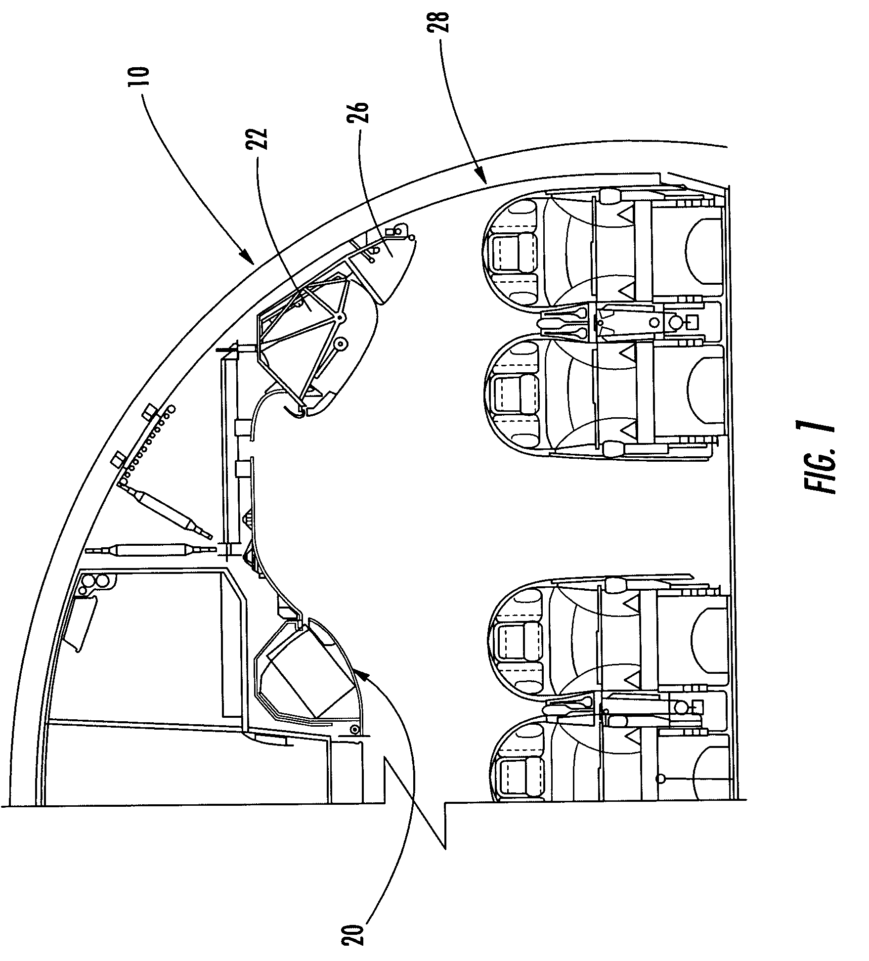
[0057]FIG. 7 is a perspective view of an inside seat gantry 200 of the present invention. An inside seat gantry may be similar to an outside seat gantry, but may be designed for use in more confined spaces, particularly designed with a more compacted frame. Thus, after the seat assembly has been transported into the interior of the vehicle while onboard the seat cart, the seat assembly may be engaged by the inside seat gantry which removes the seat assembly from the seat cart and transports and positions the seat assembly to the proper location within the vehicle which may have only limited overhead space as shown in FIG. 1.

[0058]The frame of the inside seat assembly may be sized to accommodate the seat back height and seat width of different seat assemblies. An inside gantry frame may have two leg segments 202, 204 each with two or more tubes 206, 208, 210, 212 attached by tube cross-sections 214, 215, 216, 218, 219, 220. Typically, the tubes and cross-sections may be formed of alu...

second embodiment

[0065]FIG. 8 is a perspective view of an inside seat gantry 300 of the present invention. In this embodiment, the casters 305, 306, 307, 308 have been affixed to the inside seat gantry frame in such a manner as to increase the width 308 of the wheel base while maintaining the ability to easily navigate the inside seat gantry through narrow aisles and passageways. By increasing the width 308 of the wheel base, the inside seat gantry 300 has improved stability for more easily handling seat assemblies and moving the inside seat gantry 300 while a seat assembly is suspended from the hoist. The casters 305, 306, 307, 308 may be attached to base members 310, 312 that may be aluminum box sections. The base members 310, 312 may be rotatably connected to the bottom ends 314, 316 of the leg segments of an inside seat gantry frame. Alternatively, a base member may have an adjustable width such as caster mounts that retract inboard to decrease the wheel base for moving the inside seat gantry do...

third embodiment

[0068]FIG. 10 is a perspective view of an inside seat gantry 350 of the present invention with adjustable leg lengths and frame height and a hoist 360 mounted to a leg segment 352. To lower the center of gravity of the inside seat gantry 350, the weight of the hoist 360 has been shifted from a mounting location on the upper portion of the frame to a lower side mount. The hoist 360 has been modified to provide a more compact package to allow the hoist 360 to be mounted between the two legs 354, 356 rather than the elongated space 358 defined by the upper portion of the frame. This also increases the height the seat gantry can lift a seat assembly without increasing the overall height of the seat gantry. To provide such a compact hoist package, the hoist 360 has been modified from an in-line configuration to having a parallel gear drive configuration, for example where the motor 362 is mounted parallel to the strap drum 364 with a perpendicular gear drive 366 between the motor 362 and...


PUM


Abstract

A seat gantry system and method are provided for handling, installing, and removing heavy seat assemblies, and the components thereof prevent manual lifting of a heavy seat assembly during installation. A seat gantry system or method may include an outside seat gantry, a seat cart, an inside seat gantry, and an artificial lifting torso. An outside seat gantry is used for lifting a seat assembly off a shipping platform, moving and positioning a seat assembly over a seat cart, and lowering the seat assembly onto the seat cart. A seat cart is used for transporting a seat assembly. An inside seat gantry is used for lifting a seat assembly from a seat cart and positioning and lowering the seat assembly for installation. An artificial lifting torso is used to provide a common lifting point at a balanced fore-aft center of gravity of a seat assembly.

Description

FIELD OF THE INVENTION[0001]The present invention relates generally to handling of passenger seats, and, more particularly, to and installation and removal of heavy aircraft seating.BACKGROUND OF THE INVENTION[0002]Passenger transportation seats, such as airline seats and train seats, are continually becoming more complex, and consequently heavier, particularly in the higher class seating areas such as First and Business Class accommodations. Seats now include such additional amenities as entertainment systems, Internet access, and long-range sleeper or signature features. Some of these seat assemblies including multiple seats may weigh over 500 pounds.[0003]As the weights of seat assemblies increase, traditional methods of handling and installing seats have become cumbersome, more difficult, and a physical risk to the operators. Additionally, in confined spaces, such as airline cabins, handling and installing these heavy seats are complicated by restrictions on operator movement. T...

Claims


Application Information

Patent Timeline
Patent Type & Authority Patents(United States)
IPC IPC(8): B65G67/02B62B3/00B62B3/06B62B3/12B62B5/02B64F5/00B66C19/02
CPCB62B3/002B62B3/0637B62B3/12B64F5/0036B66C19/02B62B5/0076B62B5/0093B62B3/02B62B5/02B62B2202/32B62B2205/006B64F5/50
Inventor EGGLESTON, N. CHARLESSCHAEFER, KARL J.SMITH, DAVID C.
Owner THE BOEING CO
Why Eureka
Try Eureka