Thrombectomy catheter device having a self-sealing hemostasis valve
What is Al technical title?
Al technical title is built by PatSnap Al team. It summarizes the technical point description of the patent document.
a catheter device and self-sealing technology, applied in the field of thromboscopy catheter devices, to achieve the effect of reducing friction on the guidewire and maximizing the recirculation pattern
Inactive Publication Date: 2007-06-05
BOSTON SCI LTD
View PDF7 Cites 66 Cited by
Summary
Abstract
Description
Claims
Application Information
AI Technical Summary
This helps you quickly interpret patents by identifying the three key elements:
Problems solved by technology
Method used
Benefits of technology
[0006]The general purpose of the present invention is to provide a thrombectomy catheter device having an improved and self-sealing hemostasis valve which can be preset to automatically seal with or without the inclusion of a guidewire at a certain desired pressure. Such sealing is automatic without the need to manually manipulate a hemostasis nut to obtain hemostasis. The thrombectomy catheter device can, without hemostasis nut adjustment, be positioned along and about a guidewire while yet maintaining suitable pressure or at an allowable leakage rate for sustaining hemostasis at a preferred level. Additionally, the hemostasis nut in several embodiments can be manually tightened to influence the self-sealing hemostasis valve to restrict flow or guidewire movement, or manually loosened to reduce friction on the guidewire and allow fluid to flow out, if desired. The present invention is a mechanical thrombectomy catheter device which uses high velocity saline jets shooting past a gap to entrain and macerate thrombus and other debris located within vessels by way of a low pressure zone and recirculation patterns, as described in previous patents and / or patent applications by the applicants. This basic design is further optimized using cross stream technology that has regions of inflow (low pressure) and outflow (high pressure) that maximize the recirculation pattern, among other things. The thrombectomy catheter device is primarily composed of a manifold and an exhaust line having a maceration tip which associates with and connects to commonly found thrombectomy removal systems such as, but not limited to, a pump, a high pressure supply line, and a drive unit. A cross stream effect occurs at the tip, which is described extensively in previous patents and applications by the applicants along with all of the other components. This particular improvement to this existing technology is concerned with the manifold of the device. The manifold allows for the connection of the high pressure supply line and an exhaust line, and includes structure for exiting of a guidewire which is sealed with a self-sealing hemostasis valve. The new improvement to the manifold is concerned primarily with the self-sealing hemostasis valve, although the current manifold is also improved over the old in such ways as being optimized for size, weight, manufacture, and compatibility with future improvements to the overall thrombectomy catheter system.
Problems solved by technology
This secondary dual seal is only used in extreme cases when hemostasis cannot be achieved with the automatic self-sealing hemostasis valve.
Method used
Image
Click on the blue label to locate the original text in one second.
Reading with bidirectional positioning of images and text.
Examples
Embodiment Construction
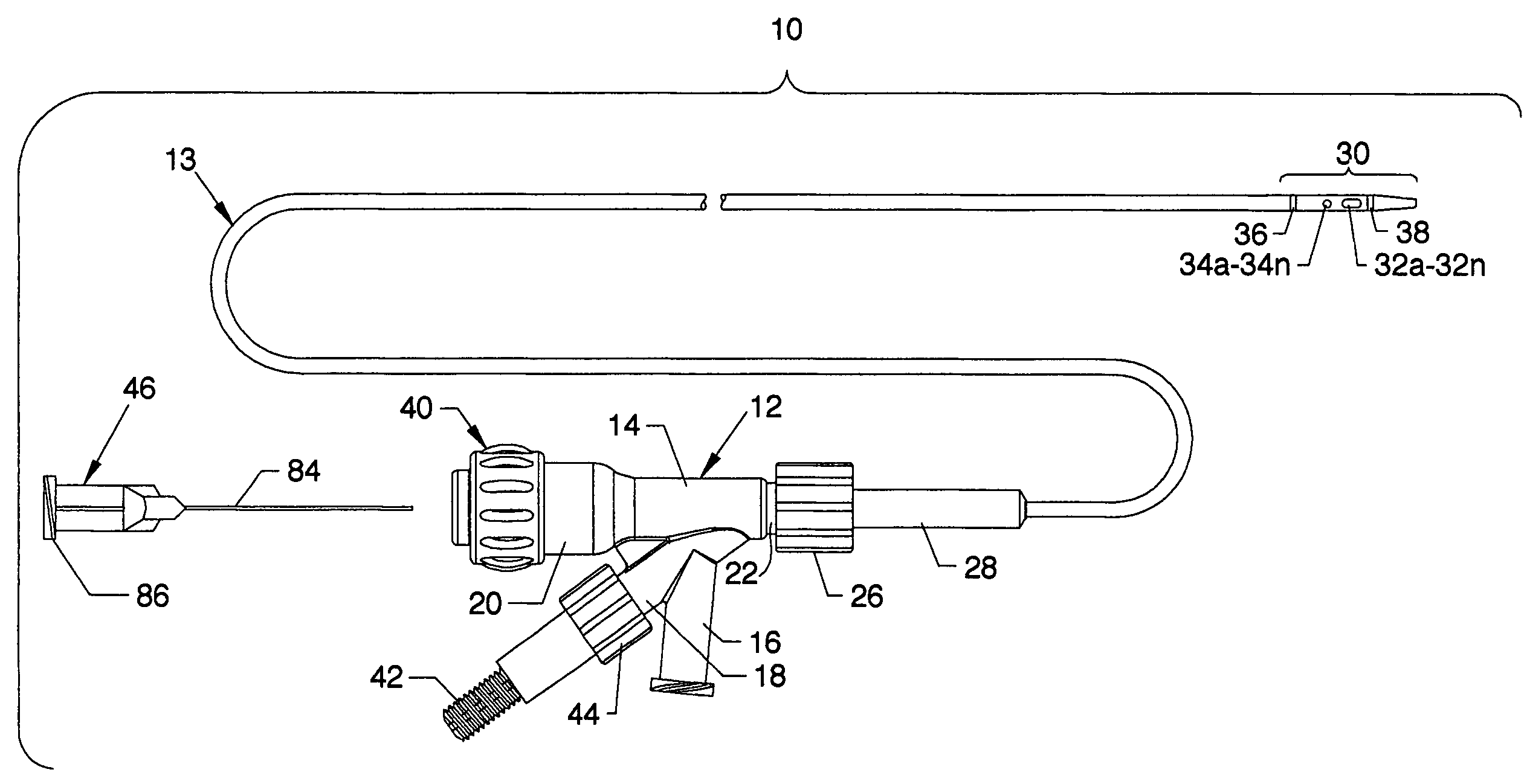
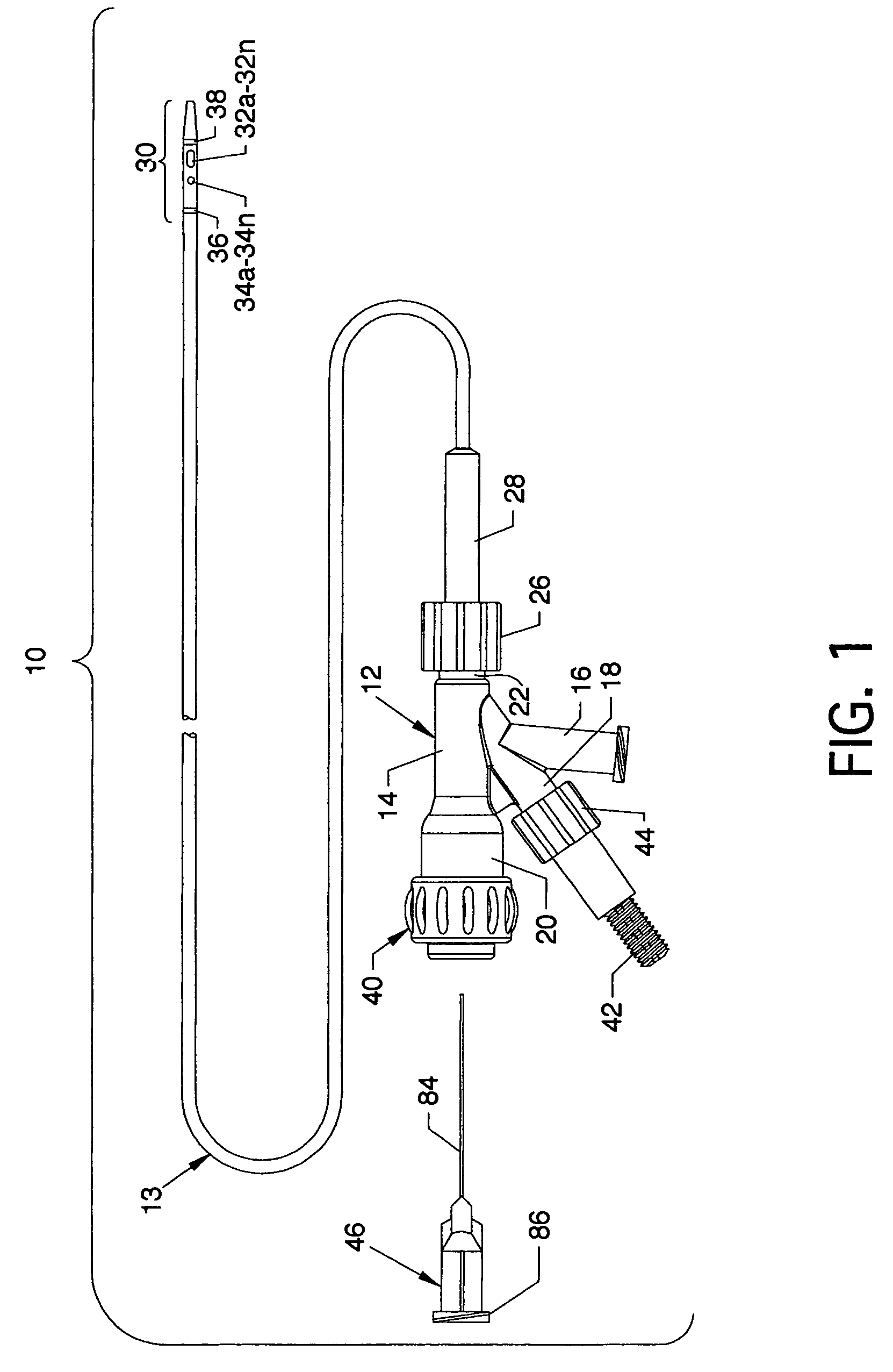
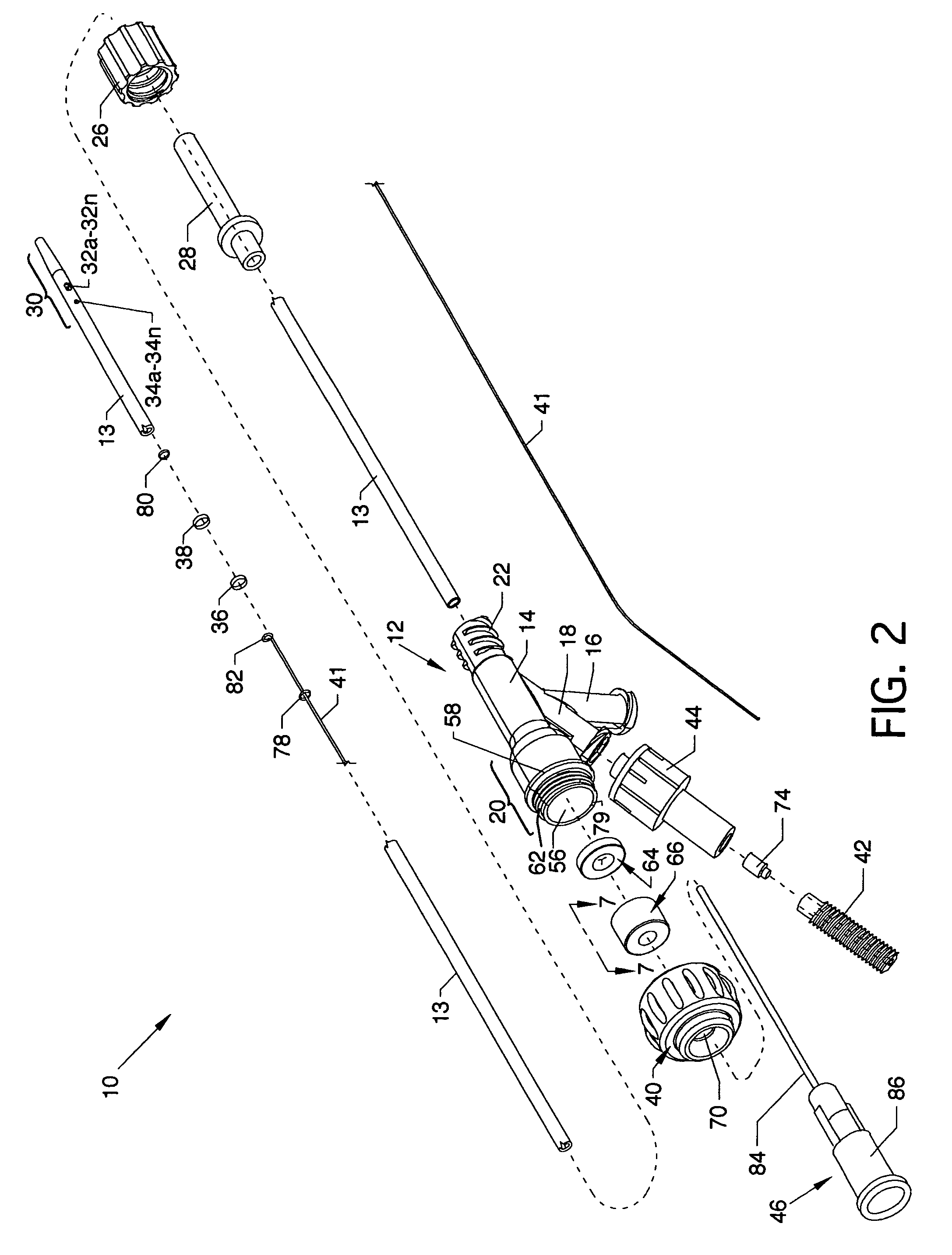
[0083]FIG. 1 is a plan view of the visible components of a thrombectomy catheter device having a self-sealing hemostasis valve 10, the present invention, including a one-piece manifold 12 having multiple structures extending therefrom or attached thereto and including a catheter tube 13 and other components as described herein. The visible portion of the one-piece manifold 12 includes a central tubular body 14, an exhaust branch 16 and a high pressure connection branch 18 extending angularly from the central tubular body 14, a cavity body 20 extending proximally from the central tubular body 14, and partially shown and extending distally from the central tubular body 14, a threaded connection port 22. The proximal end of the catheter tube 13 secures to the manifold 12 by the use of a Luer fitting 26 accommodated by the threaded connection port 22. The proximal end of the catheter tube 13 extends through a strain relief 28 and through the Luer fitting 26 to communicate with the manif...
PUM
Abstract
A thrombectomy catheter device having an improved hemostasis valve which is self-sealing and which functions as a one-way valve. The self-sealing hemostasis valve can be factory preset to automatically seal with or without the inclusion of a guidewire at a certain desired pressure or allowable leakage. Such sealing is automatic without the need to manually manipulate a hemostasis nut to obtain hemostasis. The thrombectomy catheter device can, without hemostasis nut adjustment, be positioned along and about a guidewire while yet maintaining suitable pressure for sustaining hemostasis at a preferred level. Certain embodiments of the thrombectomy catheter device having a self-sealing hemostasis valve include an adjustable hemostasis nut which can be manually tightened to restrict flow or guidewire movement or loosened to reduce friction on the guidewire and allow fluid to flow out if desired. An introducer facilitates free passage of a guidewire in either direction through the hemostasis nut and hemostasis valving and can also be incorporated to purge internal air or fluids.
Description
CROSS REFERENCES TO RELATED APPLICATIONS[0001]This patent application is a continuation-in-part of Ser. No. 10 / 198,264 entitled “Rapid Exchange Fluid Jet Thrombectomy Device and Method” filed on Jul. 16, 2002, now U.S. Pat. No. 6,875,193, which is a continuation-in-part of Ser. No. 09 / 888,455 entitled “Single Operator Exchange Fluid Jet Thrombectomy Device” filed on Jun. 25. 2001, now U.S. Pat. No. 6,755,803, which is a continuation-in-part of Ser. No. 09 / 356,783 entitled “Rheolytic Thrombectomy Catheter and Method of Using Same” filed on Jul. 16, 1999, now abandoned, which is a divisional of Ser. No. 09 / 019,728 entitled “Rheolytic Thrombectomy Catheter and Method of Using Same” filed on Feb. 6, 1998, now U.S. Pat. No. 5,989,210. Patent application Serial No. 10 / 198,264 is also related to Ser. No. 09 / 417,395 entitled “Thrombectomy Catheter and System” (as amended) filed on Oct. 13, 1999, now U.S. Pat. No. 6,676,627, which is a continuation-in-part of Ser. No. 08 / 349,665 entitled “Th...
Claims
Application Information
Patent Timeline
Application Date:The date an application was filed.
Publication Date:The date a patent or application was officially published.
First Publication Date:The earliest publication date of a patent with the same application number.
Issue Date:Publication date of the patent grant document.
PCT Entry Date:The Entry date of PCT National Phase.
Estimated Expiry Date:The statutory expiry date of a patent right according to the Patent Law, and it is the longest term of protection that the patent right can achieve without the termination of the patent right due to other reasons(Term extension factor has been taken into account ).
Invalid Date:Actual expiry date is based on effective date or publication date of legal transaction data of invalid patent.