High SBS threshold optical fiber with fluorine dopant

a fluorine dopant, high sbs threshold technology, applied in the direction of optical fibers with multi-layer cores/claddings, optical waveguide light guides, instruments, etc., can solve the problems of large loss of signal power, nonlinear penalty, and stimulated brillouin scattering (sbs) to achieve the effect of suitable performan

Inactive Publication Date: 2007-06-05
CORNING INC
View PDF4 Cites 10 Cited by
  • Summary
  • Abstract
  • Description
  • Claims
  • Application Information

AI Technical Summary

Problems solved by technology

Stimulated Brillouin Scattering (SBS) is a dominant nonlinear penalty in many optical transmission systems.
Thus, due to SBS, a large amount of the signal power can be lost due to reflection back toward the transmitter.
In addition, the scattering process increases the noise level at the signal wavelength.
The combination of decrease in signal power and increase in the noise both lower the SNR and lead to performance degradation.
The change in pressure causes material density to change, thereby resulting in refractive index fluctuations.
Above the SBS threshold level of an optical fiber, the number of stimulated photons is very high, resulting in a strong reflected field which limits the optical power that is transmitted, and which reduces the SNR.

Method used


Image

  • High SBS threshold optical fiber with fluorine dopant
  • High SBS threshold optical fiber with fluorine dopant
  • High SBS threshold optical fiber with fluorine dopant

Examples


example 1

Confining the Longitudinal Acoustic Field

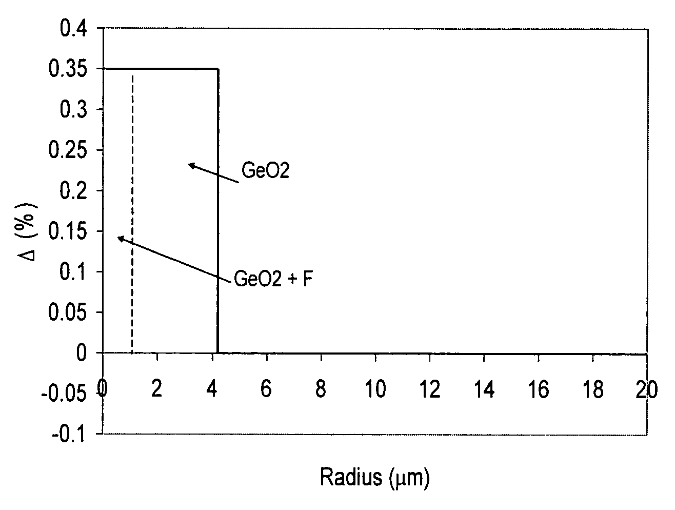
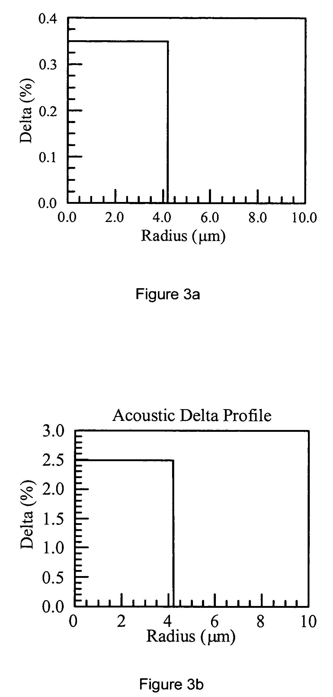
[0105]We will compare the performance of the exemplary fibers 10 with that of a standard single mode transmission fiber (fiber 1), i.e., the fiber that does not contain F and which illustrated in FIGS. 3a to 3c. We doped the core region corresponding to the radius r=0 to 2 μm (with varying level of the Fluorine while maintaining the overall optical delta profile to be the same as the fiber of FIG. 3a, so that the optical properties of the fiber, including MFD, effective area, and dispersion were essentially unchanged. The modeling results are summarized in Table 1. We found that as we increase the level of Fluorine doping in the core region 12a, the SBS threshold relative to that in fiber 1 (corresponding to FIGS. 3a and 3b) increases monotonically, which is also shown in FIG. 5.

[0106]

TABLE 10–2 μm2–4.2 μmCaseGeO2F DeltaGeO2F DeltaL01 FOMPowerOverlapNo.Delta (%)(%)Delta (%)(%)(μm2)Power (P0)Improvement (dB)Integral10.3500.35082.211.000.000.97...

example 2

Pushing the Acoustic Field away from the Center

[0108]In this example, we explore another mechanism to reduce the SBS effect. Again, we use the Ge doped step index fiber in FIG. 3a as a reference fiber. But in these embodiments we co-doped the core region 12b (r=2.5 to 4.2 microns) with fluorine dopant while leaving the core region 12a (the core region with the radius of up to 2.5 microns) unchanged. We found that as we increase the doping level of Fluorine in the region 12b as shown in Table 2, the SBS threshold increases monotonically as in FIG. 8.

[0109]

TABLE 20–2.5 μm2.5–4.2 μmCaseGeO2F DeltaGeO2F DeltaL01 FOMPowerOverlapNo.Delta (%)(%)Delta (%)(%)(μm2)Power (P0)Improvement (dB)Integral10.3500.35082.2110.000.9780.3500.38−0.0393.871.140.580.8590.3500.4−0.05113.661.381.410.70100.3500.45−0.1152.441.852.680.53110.3500.47−0.12163.001.982.970.49120.3500.49−0.14171.292.083.190.47130.3500.51−0.16178.502.173.370.45140.3500.53−0.18184.842.253.520.43150.3500.57−0.22196.002.383.770.41160.3500...

example 3

NZDSF Type of Fibers

[0114]The optical delta profile and acoustic delta profile of a typical large area NZDSF fiber is shown in FIGS. 11 and 12 respectively. This fiber has a dispersion of 4.1 ps / nm / km at 1550 nm, Kappa of 48 nm at 1550 nm, dispersion of −15.73 ps / nm / km at 1310 nm, zero dispersion around 1500 nm, MFD of 9.82 μm at 1550 nm, MFD of 7.61 μm at 1310 nm, effective area of 72.52 μm2 at 1550 nm. This fiber has an acoustic FOM of 114.35 μm2. The optical field and longitudinal acoustic fields of this fiber are shown in FIG. 13.

[0115]Now, we consider a case where we have fluorine doped at first region 12a of the fiber core (corresponding to the radius r from 0 to 1 micron) to produce delta of −0.28% and then added Ge to this region, so that the overall optical delta profile is maintained the same as that shown FIG. 11. In this case, the optical properties of the fiber such as the dispersion, MFD and optical effective area are essentially the same as the case when the delta is ...


PUM


Abstract

The optical fiber comprises: (a) a core having a refractive index profile and a centerline; and (b) a cladding layer surrounding and directly adjacent the core; wherein core includes updoping material and is doped with F in at least one region of the core, such that either: (a) the average longitudinal acoustic wave velocity within the core is within 0.05% of the longitudinal acoustic wave velocity within the cladding; or (b) the longitudinal acoustic wave velocity at one region of the core is different from the longitudinal velocity at another region of the core by at least 0.2%.

Description

[0001]This application claims the benefit of priority under 35 U.S.C. § 119(e) of U.S. Provisional Application Ser. No. 60 / 691,179 filed on Jun. 15, 2005.BACKGROUND OF THE INVENTION[0002]1. Field of the Invention[0003]The present invention relates to high SBS threshold optical fibers.[0004]2. Technical Background[0005]Stimulated Brillouin Scattering (SBS) is a dominant nonlinear penalty in many optical transmission systems. In many systems, it is desirable to transmit large amount of optical power through optical fibers, while maintaining high signal to noise ratio (SNR). However, as the optical signal power launched into an optical fiber increases, the launch power may exceed a certain threshold power (SBS threshold) and part of the optical signal power will then be reflected due to SBS as a backward propagating signal. Thus, due to SBS, a large amount of the signal power can be lost due to reflection back toward the transmitter. In addition, the scattering process increases the no...

Claims


Application Information

Patent Timeline
Patent Type & Authority Patents(United States)
IPC IPC(8): G02B6/02
CPCG02B6/02042G02B6/0281G02B6/03633G02B6/03644G02B6/02014G02B6/02266
Inventor BICKHAM, SCOTT ROBERTSONCHEN, XINLI, MING-JUNWALTON, DONNELL THADDEUS
Owner CORNING INC
Why Eureka
Try Eureka