
Method and system for automatically determining lines of sight between nodes

a technology of infrared mesh network and automatic determination, which is applied in the field of wireless infrared mesh network for automatically determining lines of sight between nodes, can solve the problems of slow consumer connection, large media file size, and inability to receive large media files, and the ability of commercial services to provide rich, and the effect of rapidly outstripping the ability of the typical consumer to receive those files

Inactive Publication Date: 2007-06-05
OMNILUX
View PDF24 Cites 229 Cited by
  • Summary
  • Abstract
  • Description
  • Claims
  • Application Information

AI Technical Summary

Benefits of technology

[0021]The present invention uses data from several sources to determine lines-of-sight between nodes in a FSO network. The present invention provides a three-dimensional neighborhood modeling system that uses aerial image data, Digital Elevation Models, U.S. street map data and address data to automatically map the placement of nodes within a neighborhood or other geographical area. While not thus limited, the network of the present invention can be cost-effectively extended to many areas not supporting traditional wired network infrastructure.

Problems solved by technology

While commercial services often choose fast but expensive high-speed Internet connections for business purposes, consumer connections typically use relatively slow telephone modems.
High-bandwidth applications such as on-demand television and Web pages filled with multimedia effects may be impossible to use with a standard telephone modem connection.
It is obvious that the ability of commercial services to provide rich, large media files is rapidly outstripping the typical consumer's ability to receive those files.
Both cable and DSL modems are priced at approximately twice the cost of telephone modem services, with slightly higher costs for equipment.
The higher speed cable and DSL connections are geographically limited, however, by the underlying infrastructure.
Many areas of the United States include regions not serviced by cable television or where the cable television network has not and will not be upgraded to support high-speed data modems.
Similarly, DSL service is not available in many geographic areas.
Numerous reasons exist for the limited availability of cable and DSL services, including high-cost of infrastructure upgrade, technological limitations, physical geographical limitations and, in some areas, low demand.
As with many types of commercial services, the incremental costs of extending infrastructure become increasingly higher, sometimes by multiples or even exponentially, as attempts are made to expand those infrastructures to every last consumer.
RF networks however cannot provide a level of security that is required by many broadband users.
In addition, FSO works in an unregulated frequency spectrum with little or no traffic currently in this range.
However, for a number of reasons, FSO systems have generally not been used as a solution to the last-mile-access problem in the past.
While lasers are a cost-effective high-speed communications medium, they require very highly aligned line-of-sight paths.
More specifically, existing FSO systems have very narrow beam divergence parameters requiring precision alignment.
For this reason, laser components tend to be expensive and laser systems tend to require high levels of maintenance and service.
In addition, FSO systems can be limited by rain, dust, snow, fog or smog that can block the transmission path and shut down the network.
Therefore, FSO deployments have been located relatively close to big hubs, which has heretofor limited the technology to customers in major cities.
There exists demand for high-speed, affordable Internet connections in geographics and neighborhoods into which more traditional, wired high-speed network infrastructure cannot be cost-effectively extended.
While FSO systems have been developed, significant obstacles have prevented widespread use of FSO systems to achieve last-mile access.
One significant obstacle to implementing FSO networks is the difficulty of setting up the IR nodes such that an unobstructed line-of-sight is achieved between nodes.

Method used


Image

  • Method and system for automatically determining lines of sight between nodes
  • Method and system for automatically determining lines of sight between nodes
  • Method and system for automatically determining lines of sight between nodes

Examples


Embodiment Construction

[0038]With reference now to the drawing Figures, embodiments of the invention are shown and described wherein like elements are indicated by like reference numerals throughout.

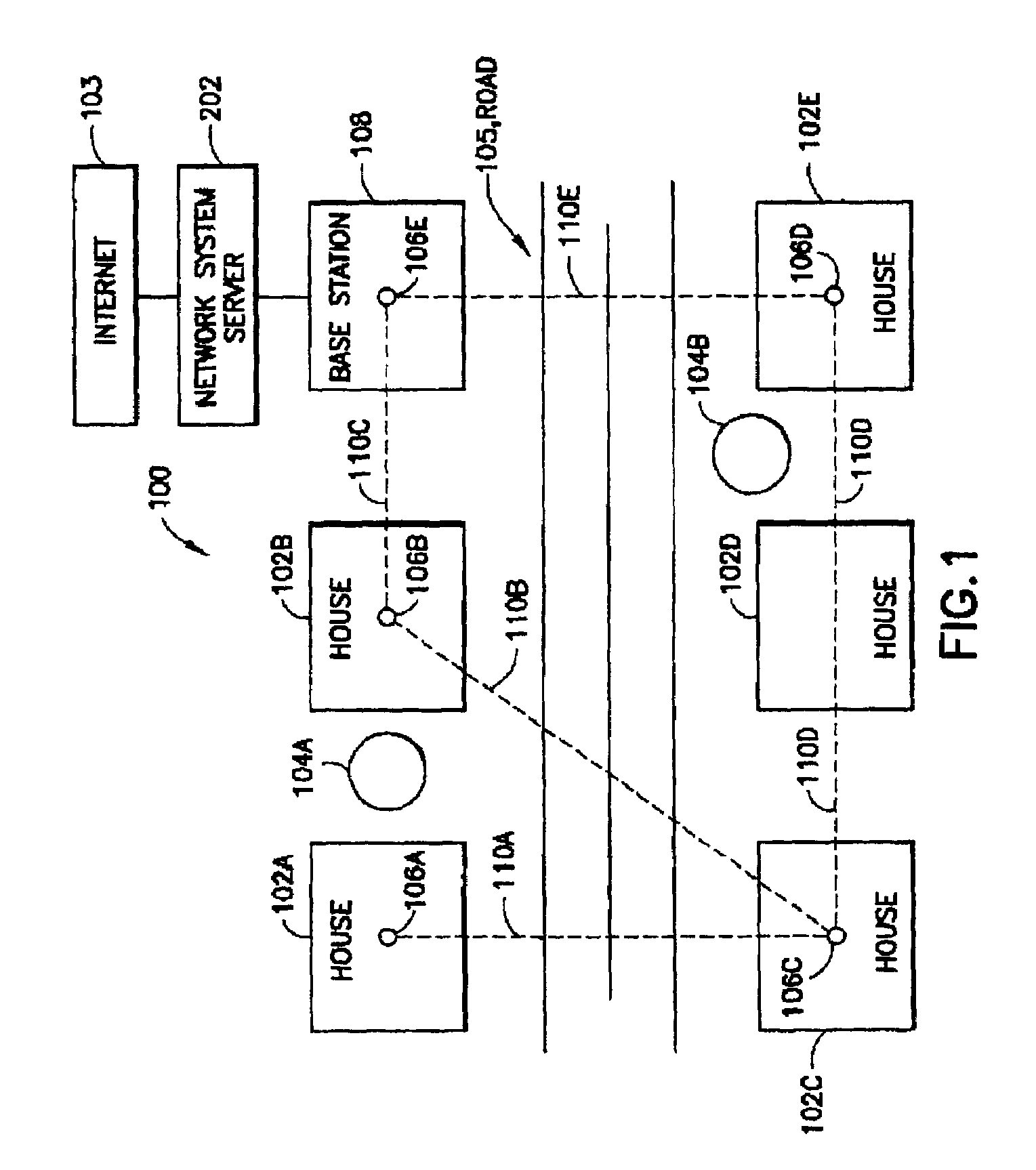
[0039]With reference first to FIG. 1, a diagram of a residential neighborhood 100 is shown including multiple houses indicated at 102A–E. As is typical in neighborhoods, trees or other natural obstacles exist, indicated at 104A&B, which may block lines of sight between adjoining houses. In accordance with the present invention, a series of infrared network nodes, indicated at 106A–E, are positioned on the upper, outer surfaces of the homes, for example the roofs. Note that house 102D has elected not to receive services from the described network, and so no network node is positioned on that house. Although only houses are shown in FIG. 1, it will be obvious to those skilled in the art that the nodes may be mounted on structures other than houses, such as apartment building, office buildings and the like. It is...


PUM


Abstract

The present invention uses data from several sources to determine lines-of-sight between nodes in a FSO network. The present invention provides a three-dimensional neighborhood modeling system that uses aerial image data, Digital Elevation Models, U.S. street map data and address data to automatically map the placement of nodes within a neighborhood or other geographical area.Method for creating the 3-Dimensional, House and Tree Maps used in the line-of-sight processing are also disclosed. A House Map in the present invention identifies houses in an area of consideration, and a Tree Map in the present invention identifies trees in an area of consideration. A 3-Dimensional Map in the present invention provides an elevation for every pixel for the area under consideration, whereby the elevation is adjusted for the height of trees, houses and other objects.

Description

[0001]This application is a divisional of U.S. patent application Ser. No. 10 / 153,878, filed May 24, 2002 now U.S. Pat. No. 6,771,932, which is incorporated herein by reference.FIELD OF THE INVENTION[0002]The present invention relates generally to wireless networks and more particularly to a method for determining lines of sight between two noes in a wireless infrared mesh network.BACKGROUND OF THE INVENTION[0003]In many areas of the world the World Wide Web (WWW), or Internet, has become a significant medium for the exchange of information including everything from casual electronic mail (e-mail) to legal and business documents to entertainment media. Much of the material exchanged over the Internet comprises very large electronic files, for example large documents, music, video and even full-length motion pictures are available for exchange and distribution over the Internet.[0004]While commercial services often choose fast but expensive high-speed Internet connections for busines...

Claims


Application Information

Patent Timeline
IPC IPC(8): H04B5/00H04W16/18
CPCH04W16/18
Inventor MOURSUND, CARTERCAMINITI, LORENZODI BERNARDO, ENRICOGONCALVES, LUIS
Owner OMNILUX
Learn More