Location estimation in wireless telecommunication networks

a wireless telecommunication network and wireless technology, applied in the direction of frequency-division multiplex, transmission monitoring, instruments, etc., can solve the problem of rapid degradation of data bases

Active Publication Date: 2007-06-05
AIRWAVE LOCATION TECH LLC
View PDF17 Cites 232 Cited by
  • Summary
  • Abstract
  • Description
  • Claims
  • Application Information

AI Technical Summary

Benefits of technology

[0026]An advantage of the invention is that prior information on the network infrastructure is not necessary (although it may be useful). This means that a location service according to the invention is not tied to network operators. Even if the location service according to the invention is maintained by a network operator, that operator can exploit observations from other operators networks without prior information on their infrastructure. The invention is applicable in a wide variety of network techniques, such as cellular networks, broadcast networks or wireless local-area networks.
is that prior information on the network infrastructure is not necessary (although it may be useful). This means that a location service according to the invention is not tied to network operators. Even if the location service according to the invention is maintained by a network operator, that operator can exploit observations from other operators networks without prior information on their infrastructure. The invention is applicable in a wide variety of network techniques, such as cellular networks, broadcast networks or wireless local-area networks.

Problems solved by technology

At first sight, it would seem that the databases will deteriorate rapidly, unless constantly updated.

Method used


Image

  • Location estimation in wireless telecommunication networks
  • Location estimation in wireless telecommunication networks
  • Location estimation in wireless telecommunication networks

Examples


performance examples

Example 1

Location Estimation with a Naïve Bayes Model

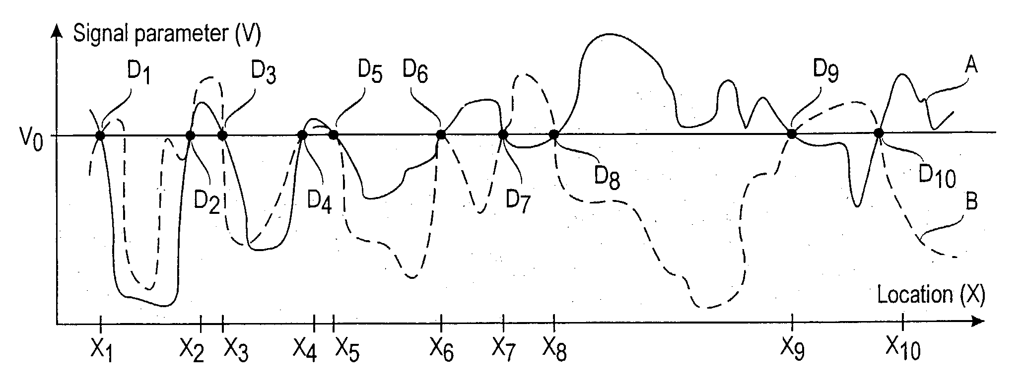
[0081]The subareas X under consideration are the locations where the calibration data was collected. The radius of the locations is assumed to be one meter, although any unit can be used. The observational variables V are taken to be discrete with m values. The value of m can be a constant (eg 3), or it can be optimized by using one of the weighting functions described above. The boundary points between the intervals can be determined so that the number of training samples within each interval is the same (equal-frequency discretization), or alternatively, the intervals can be made of equal width (equal-width discretization). The intervals can also be determined by using a clustering algorithm, such as the K-means algorithm.

[0082]One model structure M is used: the observational variables V1, . . . ,Vn are assumed to be independent, given the value of the location variable X. The data is assumed to be independently and identically ...

example 2

Location Estimation with a Mixture of Histograms Model

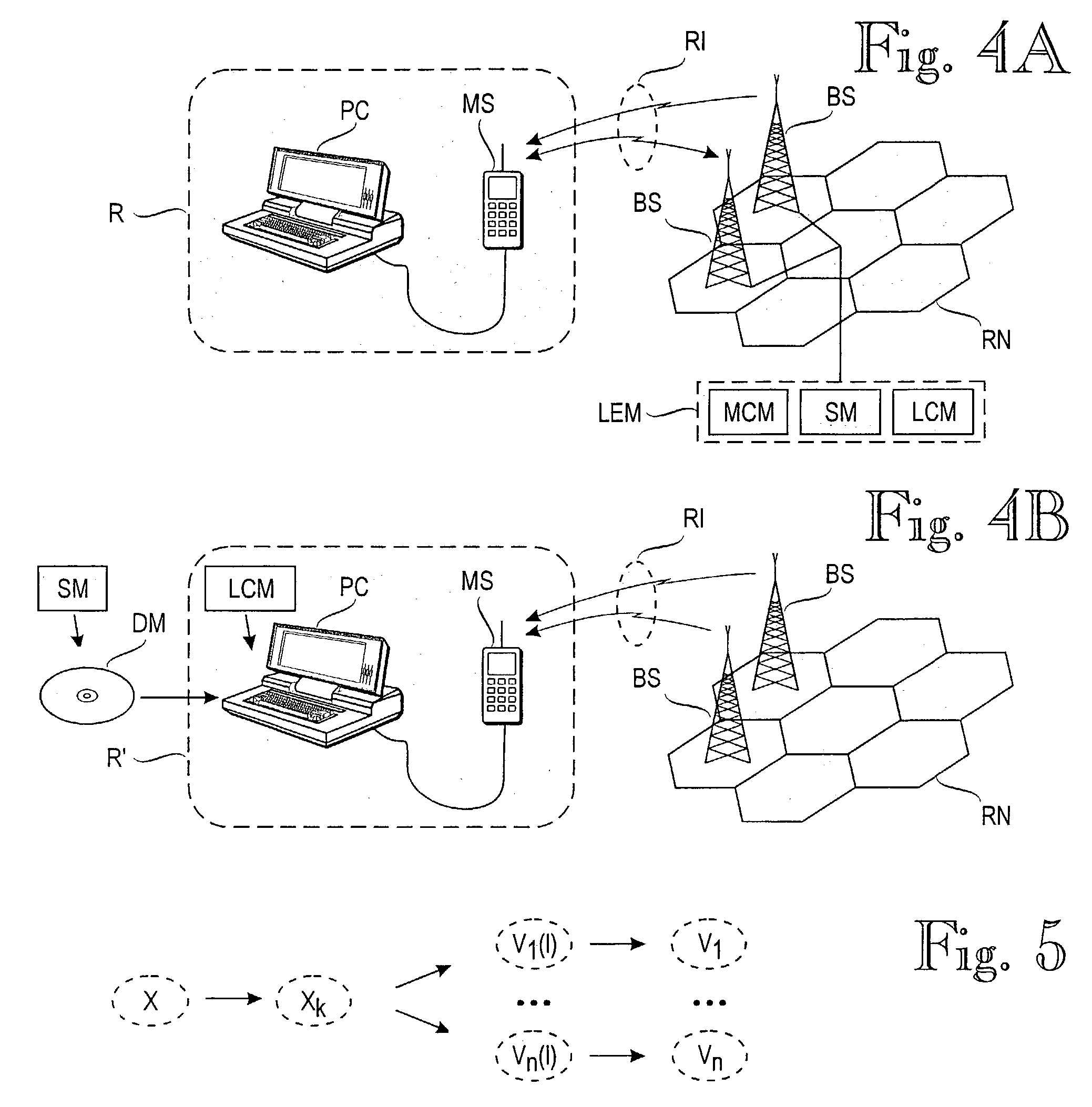
[0085]The location variable X is taken to consist of two coordinates (one or three coordinates are also possible) on a fine-grained, discrete scale. The resolution of the scale can be, for instance, one meter. The observational variables V1, . . . , Vn are taken to be discrete with the maximum resolution determined by the measuring device, e.g. 1 dBm. We denote the combination of V1, . . . , Vn by V. Missing values are replaced by a value which is smaller than any possible observable value. Several models are considered. Each model Mkl is associated with parameters k, l, and θkl whose semantics is described below.

[0086]FIG. 5 illustrates the structure of model Mkl. The value of variable Xk is obtained from the value of variable X via discretization into k values. The conditional distribution of variables V1(I) , . . . , Vn(I) given the value of Xk is described by model parameters θkl. Each Vi, where i belongs to the set {1, . . ....


PUM


Abstract

A method for estimating a receiver's location in a wireless communication environment having several channels. Each channel has at least one signal parameter that varies with location differently from the other channels. A set of calibration data is determined for each calibration point, each set including the location and at least one measured signal parameter for each of several channels. The calibration data serve as a basis for a statistical model of the signal parameters versus a receiver's location. A set of observed signal parameters is determined, the set including at least one signal parameter for each of several channels at the receiver's location. A location estimate approximating the location of the receiver is determined on the basis of the statistical model and the set of observed signal parameters.

Description

[0001]This application is a Continuation of International Application PCT / F101 / 01151 filed Dec. 27, 2001, which designated the U.S. and was published under PCT Article 21 (2) in English.BACKGROUND OF THE INVENTION[0002]The invention relates to methods and equipment for estimating a receiver's location in a wireless telecommunication environment, ie one or more networks which may be radio, microwave or optical networks. The one or more networks communicate at a plurality of channels simultaneously. Such a location estimation can be used to provide a wide variety of location-dependent services.[0003]U.S. Pat. No. 6,112,095 to Mati Wax et al. discloses a method for providing a set of likely locations of a transmitter in a cellular network, such as AMPS or CDMA. A problem with the technique disclosed in the Wax patent is that it requires additional hardware at the network side, such as an antenna array which is equipped to measure an angular direction relative to a base station. In othe...

Claims


Application Information

Patent Timeline
Patent Type & Authority Patents(United States)
IPC IPC(8): H04Q7/20G01S19/11G01S5/02H04B17/00H04W64/00
CPCG01S5/02G01S5/0252H04W64/00G01S5/02521
Inventor MYLLYMAKI, PETRITIRRI, HENRYKONTKANEN, PETRILAHTINEN, JUSSISILANDER, TOMIROOS, TEEMUTUOMINEN, ANTTIVALTONEN, KIMMOWETTIG, HANNES
Owner AIRWAVE LOCATION TECH LLC
Why Eureka
Try Eureka