Alignment compensator for magnetically attracted inspecting apparatus and method

a technology of alignment compensation and magnetically attracted probes, which is applied in the direction of instruments, specific gravity measurement, magnetic property measurement, etc., can solve the problem that the probes may not be accurately aligned, and achieve the effect of reducing the necessary sophistication and improving the inspection of the structur

Inactive Publication Date: 2007-06-12
THE BOEING CO
View PDF17 Cites 26 Cited by
  • Summary
  • Abstract
  • Description
  • Claims
  • Application Information

AI Technical Summary

Benefits of technology

[0013]An improved apparatus and method for inspecting a structure, such as a composite structure, especially a curved composite structure, compensates for misalignment of magnetically attracted probes. An inspection apparatus or method using an alignment compensator of the present invention may advantageously improve inspection of a structure, such as continuous inspection of a large area of a structure, by maintaining alignment and positioning of sensing transducers and / or receivers. The method and apparatus of the present invention use probes including respective sensing elements, such as ultrasonic transducers, that are disposed proximate the opposed surfaces of a structure. Only one of the probes need be driven. Either probe or both probes may include an alignment compensator for aligning the two probes with respect to each other. However, because only one probe need be driven, the probes may not be accurately aligned beyond the rough alignment provided by the magnetic coupling between the probes. Thus, the method and apparatus of the present invention are advantageously adapted to align probes for inspection of structures in which a surface of the structure is relatively inaccessible. Further, embodiments of the method and apparatus of the present invention permit alignment of probes that may be suspended against and glide or contact and ride along the respective surfaces of the structure. Thus, embodiments of the present invention may reduce the necessary sophistication of the motion control system that is otherwise required by conventional scanning systems to maintain the ultrasonic probes in a predefined orientation and at a predefined spacing from the respective surface of a structure undergoing inspection and may maintain alignment between the probes or the sensors of the probes.

Problems solved by technology

However, because only one probe need be driven, the probes may not be accurately aligned beyond the rough alignment provided by the magnetic coupling between the probes.

Method used


Image

  • Alignment compensator for magnetically attracted inspecting apparatus and method
  • Alignment compensator for magnetically attracted inspecting apparatus and method
  • Alignment compensator for magnetically attracted inspecting apparatus and method

Examples


Embodiment Construction

[0040]The present invention will be described more fully with reference to the accompanying drawings. Some, but not all, embodiments of the invention are shown. The invention may be embodied in many different forms and should not be construed as limited to the embodiments described. Like numbers and variables refer to like elements and parameters throughout the drawings.

[0041]Alignment compensators are described with respect to an apparatus having magnetically attracted probes. The description of alignment compensators of the present invention appears under the heading Alignment Compensation in Section II and follows this description of magnetically attracted probes.

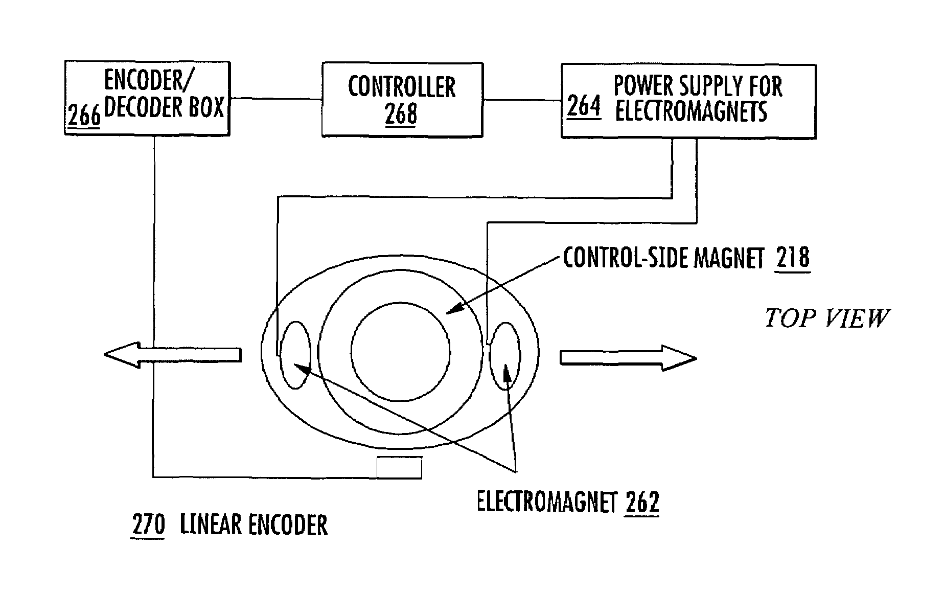
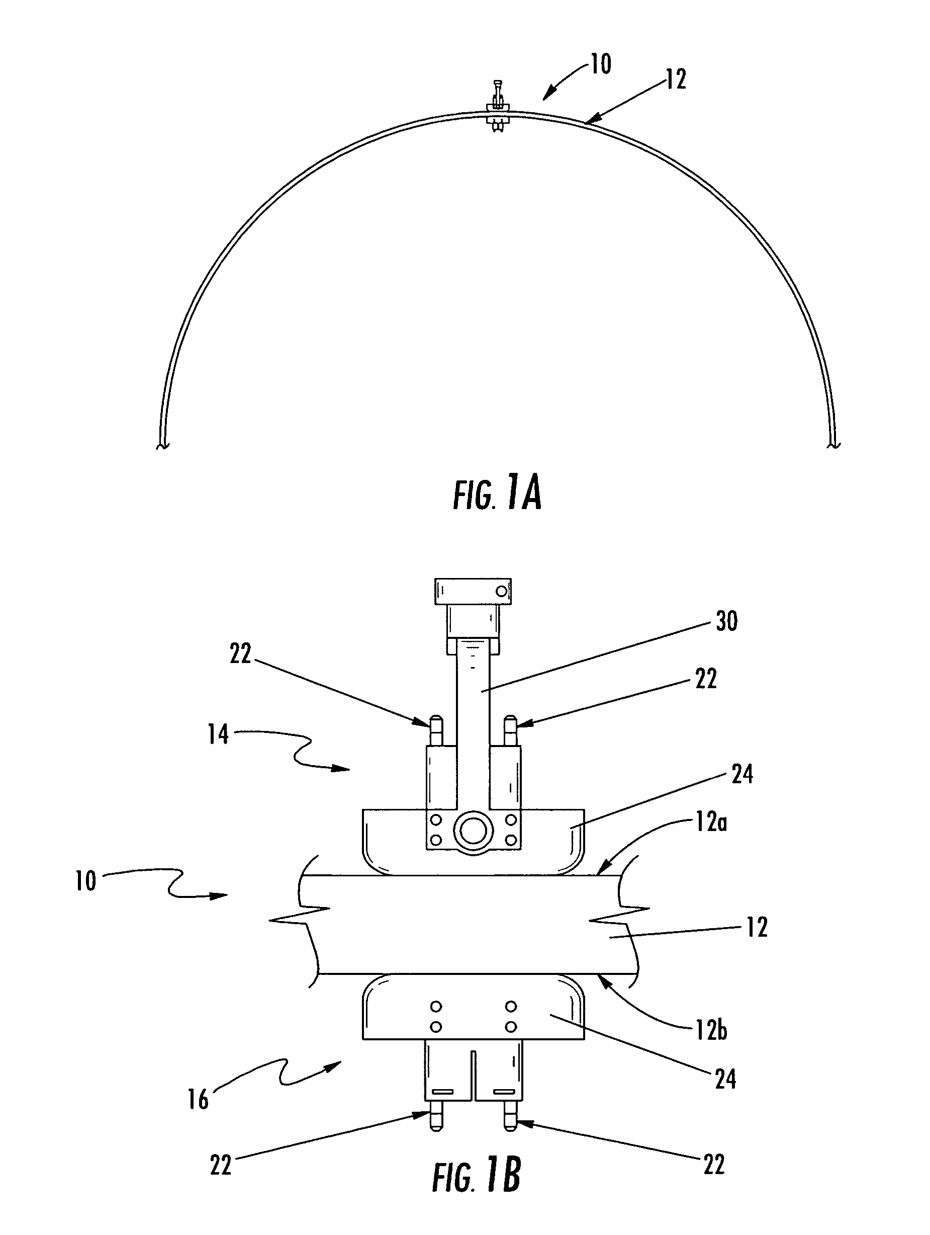
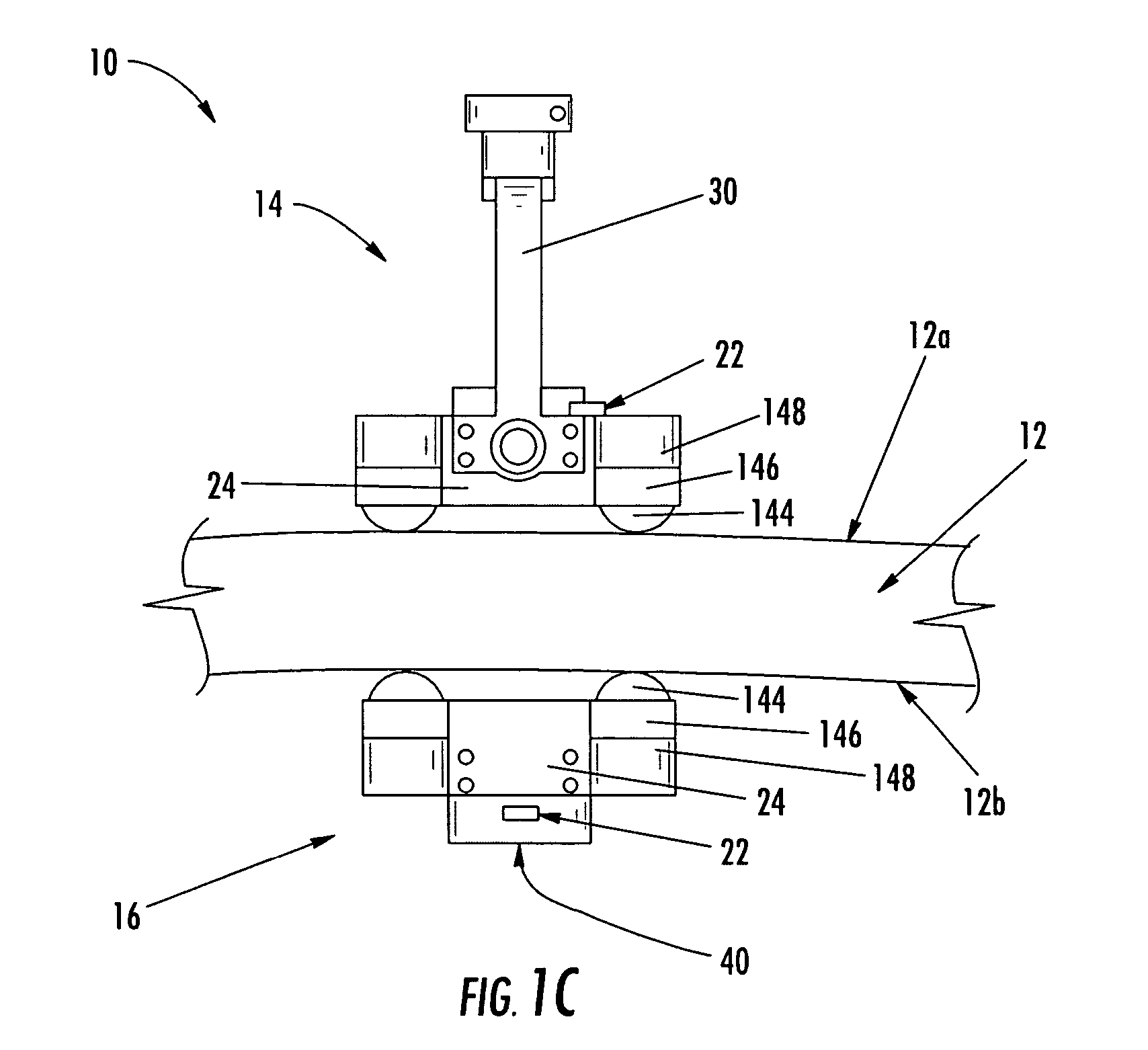
[0042]I. Magnetically Attracted Inspection Probes

[0043]An apparatus having magnetically attracted probes includes a driven probe disposed proximate a first surface of the structure and a tracking probe disposed proximate an opposed second surface of the structure. The driven probe is moved along the first surface of the ...


PUM

PropertyMeasurementUnit
lengthaaaaaaaaaa
lengthaaaaaaaaaa
diameteraaaaaaaaaa

Abstract

An apparatus and method aligning magnetically coupled inspection probes are provided. In this regard, a tracking probe may be magnetically coupled to a driven probe and move in coordination therewith. An alignment compensator for magnetically coupled inspection probes offsets misalignments between a driven probe and a tracking probe. Misalignments between magnetically coupled probes may be caused by gravity, friction, and movement of the probes. An alignment compensator may use one or more magnets, or electromagnets, to improve the alignment of the probes. An alignment compensator may include a control system for adjusting the power to an electromagnet or repositioning a magnet to offset misalignment of probes.

Description

CROSS-REFERENCE TO RELATED APPLICATIONS[0001]The contents of co-pending applications filed concurrently herewith and entitled “Magnetically Attracted Inspecting Apparatus and Method Using a Fluid Bearing,”“Magnetically Attracted Inspecting Apparatus and Method using a Ball Bearing,”“Apparatus and Method for Area Limited-Access Through Transmission Ultrasonic Inspection,” and “End Effector Inspection Apparatus and Method” are incorporated by reference in their entireties. The contents of U.S. Pat. No. 6,722,202 to Kennedy are incorporated by reference in its entirety.FIELD OF THE INVENTION[0002]The present invention relates generally to an apparatus and method for inspecting a structure and, more particularly, to an apparatus and method for aligning magnetically attracted probes for inspecting a structure.BACKGROUND[0003]Non-destructive inspection (NDI) of structures involves thoroughly examining a structure without harming the structure or requiring significant disassembly of the st...

Claims


Application Information

Patent Timeline
Patent Type & Authority Patents(United States)
IPC IPC(8): G01N9/24
CPCG01N29/265G01N2291/048G01N2291/102G01N2291/2634
Inventor GEORGESON, GARY E.FOGARTY, MICHAEL D.
Owner THE BOEING CO
Why Eureka
Try Eureka