Apparatus for dispensing paint and stain samples and methods of dispensing paint and stain samples

a technology for paint and stain samples and apparatus, which is applied in the direction of liquid transfer devices, packaging goods types, liquid handling, etc., can solve the problems of inability to adequately determine, paint retailers have no convenient means of providing paint formulations, and consumers are often surprised how the selected paint formulation actually looks on the wall or other surface, etc., to achieve the effect of convenient recall

Active Publication Date: 2007-06-12
FLUID MANAGEMENT LLC
View PDF57 Cites 52 Cited by
  • Summary
  • Abstract
  • Description
  • Claims
  • Application Information

AI Technical Summary

Benefits of technology

[0019]In a refinement, the plug receives a disposable line or cup that captures drips and that can be discarded thereby eliminating the need to clean the plug.
[0021]In the preferred refinement, the open top of the plug mateably receives the lower end of the manifold to isolate the manifold from the ambient atmosphere when the system is in a closed position. In another preferred refinement, either the open top of the plug or the lower end of the manifold comprises a seal ring to provide a seal between the plug and the manifold when the system is in the closed position. This seal ring can also act to provide a seal against the container rim when the system is in the dispensed position to reduce or eliminate the possibility of splashing outside of the container during the dispense operation.
[0024]In another refinement, the manifold accommodates a plurality of nozzles, with each nozzle being connected to an outlet of a pump in a conventional manner, such as a flexible hose. Each pump is then connected to a container which holds either base material or one of a variety of tints. Preferably, the base materials and tints are contained within a flexible package that is supported in a suitable holder such as a box or an improved bracket as described below. As noted above, each pump is linked to a controller having a memory with the memory storing a plurality of formulas that may be easily recalled by an operator. The controller is also linked to an input device for enabling the operator to select from one of a plurality of color formulas. The formulas relate to a particular paint or stain color.

Problems solved by technology

Referring generally to the paint and stain retail industry, a problem exists in that consumers are often unable to adequately determine how an actual paint color (i.e., a selected paint formulation) or a stain color (i.e., a selected stain formulation) will look on the applied surface based upon the consumer's impression of the color from a color wheel or color “swatch.” Simply put, the consumer is often surprised how the selected paint formulation actually looks on the wall or other surface.
However, a quart, a pint or even a cup of paint or stain generally far exceeds the actual amount a consumer needs to test a color on a wall or other surface.
Currently, paint retailers have no convenient means for providing paint formulations in small bottles or containers such as one or two fluid ounces.
Another problem associated with dispensing systems that make use of nozzles lies in the dispensing of relatively viscous liquids such as tints, colorants and base materials for paints that have relatively high viscosities.
If the nozzles are not cleaned regularly, they may clog thereby causing a build-up of pressure in the line which may be eventually overcome by the pump resulting in a violent splattering of fluid during a dispense.
While some mechanical wiping or scrapping devices are available, these devices are not practical for multiple nozzle manifold systems because of cross contamination of ingredients that are dispensed from the separate nozzles and further the scraper or wiper element must be manually cleaned anyway.
Another problem associated with the dispensing of paints and stains is unwanted dripping from the nozzles after a dispense operation is completed.
A drip “hanging” from a nozzle may mean that the previous formulation was not accurately dispensed.
Further, dripping of tints or colorants on the dispenser between dispensing operations results in an unsightly appearance that must be cleaned, particularly when the dispenser is used in a retail environment.
Also, a drip hanging from a nozzle may find its way into a subsequently dispensed formulation, thereby compromising the accuracy of the subsequently dispensed formulation.
To date, applicants are not aware of any attempts to provide any sort of nozzle or manifold closure or sealing element for a paint or stain dispenser that would protect against unwanted drips, that would reduce the frequency in which the nozzle or manifolds must be cleaned and that would also accommodate small, sample-sized containers.

Method used


Image

  • Apparatus for dispensing paint and stain samples and methods of dispensing paint and stain samples
  • Apparatus for dispensing paint and stain samples and methods of dispensing paint and stain samples
  • Apparatus for dispensing paint and stain samples and methods of dispensing paint and stain samples

Examples


Embodiment Construction

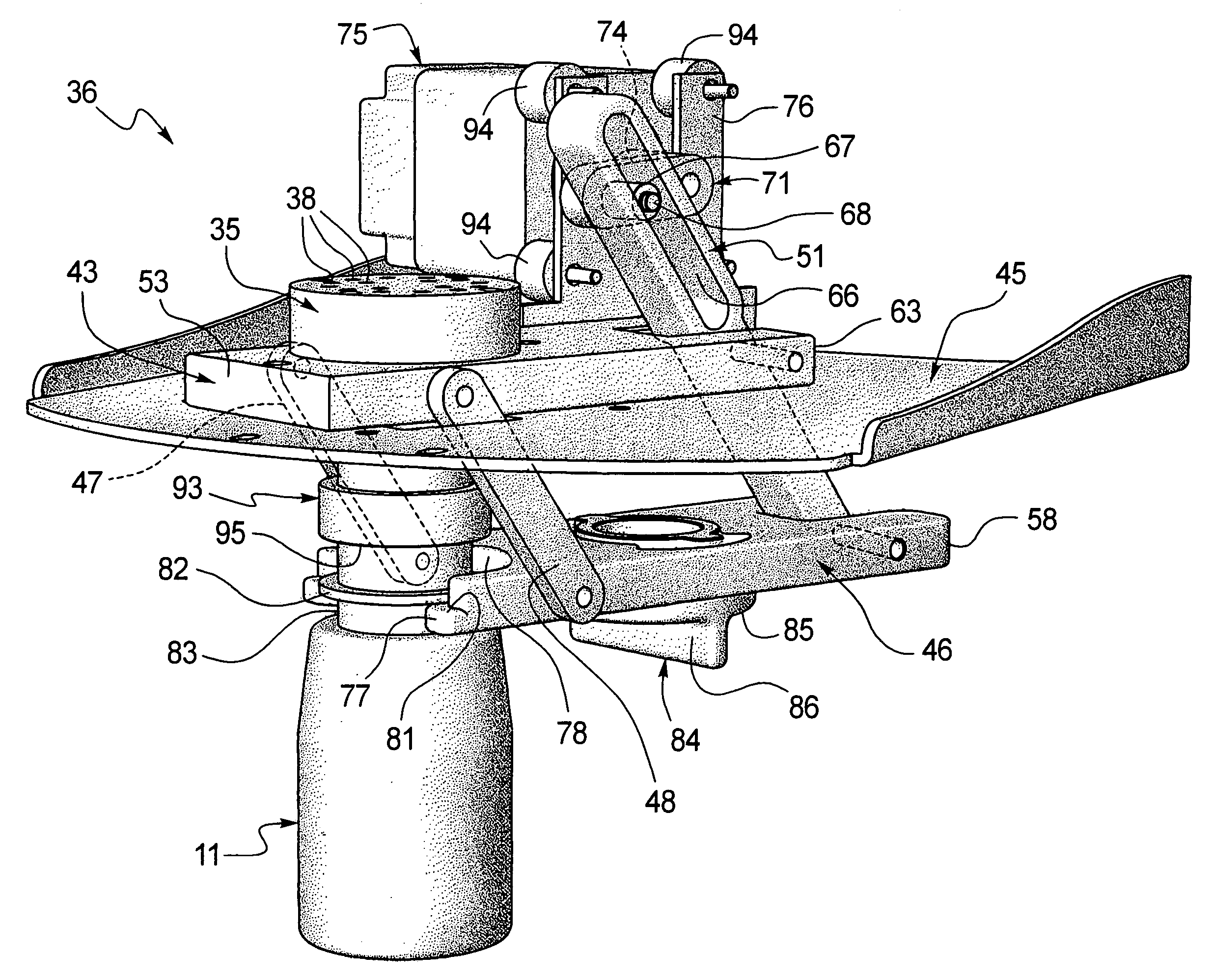
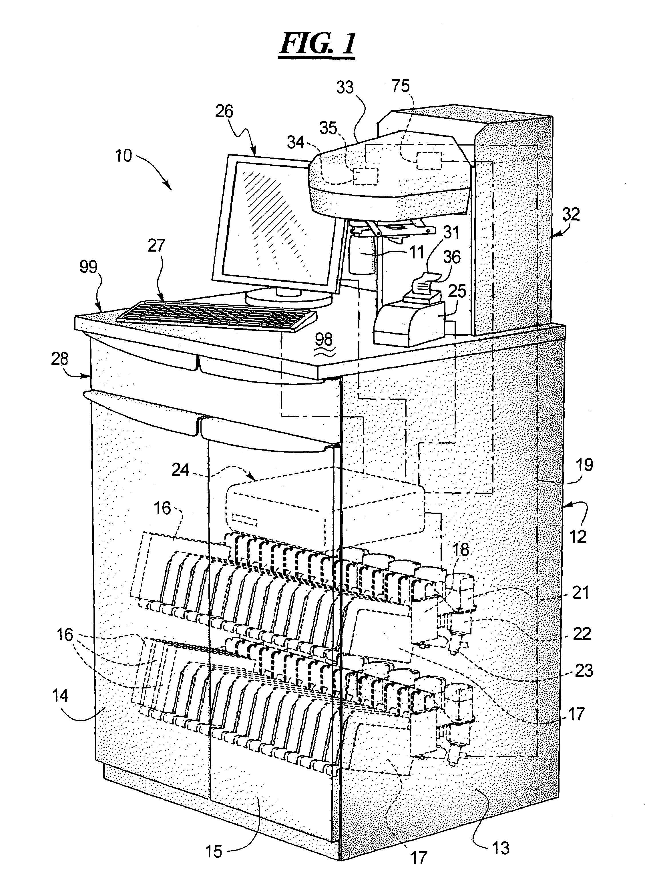
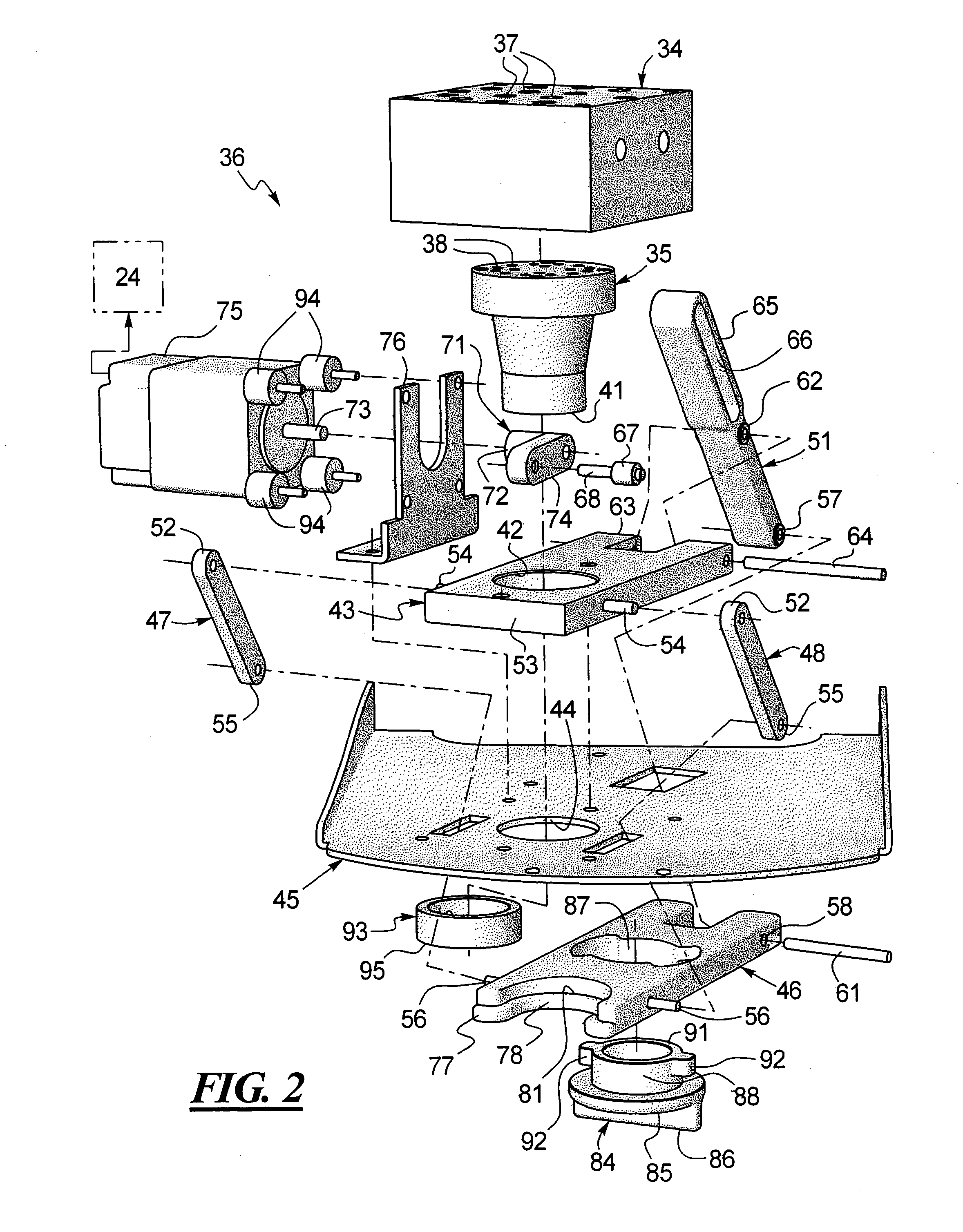
[0050]Turning to FIG. 1, a dispensing system 10 is illustrated which may be used to dispense sample-sized formulations, such as paint and stain formulations or other liquid products, into a sample-sized container 11 as well into larger containers (not shown). The system 10 includes a lower cabinetry 12 which includes a pair of opposing sidewalls, one of which is shown at 13 that are hingedly connected to front doors shown at 14, 15. The cabinetry 12 is preferably designed to house a plurality of different fluid components such as those contained within a flexible bag (not shown) disposed within a box 16. As shown generally in FIG. 1, the fluid components housed within the boxes 16 are supported by a plurality of holders shown at 17 which, in turn, are supported by brackets shown at 18, each of which is connected to a motor 21 which, in turn, operates a separate pump 22 which, in turn, is connected to the fluid reservoir (not shown) disposed within a box 16 by the nozzle assembly sho...


PUM

PropertyMeasurementUnit
rotationaaaaaaaaaa
flexibleaaaaaaaaaa
sizeaaaaaaaaaa

Abstract

An improved fluid dispenser specially adapted to provide sample-size amounts of a fluid mixture is shown and described. An automated closure and seal system is provided for the manifold that moves, on command from a controller, from a closed or sealed position thereby limiting exposure of the manifold and fluid outlet nozzles from the ambient atmosphere, to a dispense system where a sample-size container is held up against and engaging a lower end of the manifold for a sealing element disposed on a lower portion of the manifold. When the dispense is complete, the system automatically moves back toward a closed position where the filled container is held open and ready to be removed by a technician before it is capped and labeled.

Description

TECHNICAL FIELD [0001]An improved apparatus for dispensing sample-size amounts of fluid mixtures is shown and described. The improved apparatus may be adapted to dispense both sample-size amounts of fluid mixtures as well as larger quantities of said mixtures. A particular mixture is selected and retrieved from the memory of the controller and then dispensed into a sample bottle that is accommodated in a holder that is part of an automated mechanical closure system that places the bottle beneath the dispensing manifold. After the selected fluid mixture is dispensed, the bottle is automatically moved out from under the manifold, the manifold is automatically enclosed or sealed by a plug or cap, the operator places a cap on the sample bottle and the system prints a label for identifying the particular fluid mixture in the sample bottle. The bottle may then be placed in a shaker for mixing. If the consumer is satisfied after testing the sample, the label is then used to duplicate the f...

Claims


Application Information

Patent Timeline
Patent Type & Authority Patents(United States)
IPC IPC(8): B67C3/26B01F13/10F16K23/00
CPCF16K23/00B01F13/1069B01F13/10B05B15/50B01F33/80B01F33/848
Inventor MILLER, WILLIAM A.MARTIN, JAMES A.KHOO, CHRISTOPHER K.MUMFORD, JEFFREY
Owner FLUID MANAGEMENT LLC
Why Eureka
Try Eureka