Backlight using surface-emitting light sources

a surface-emitting light source and backlight technology, which is applied in the direction of lighting and heating apparatus, point-like light sources, instruments, etc., can solve the problems of limiting the projected growth of ccfl lamps, warping or otherwise damaging one or more of the optical film components, and ccfl lamps contain mercury and other issues, to achieve uniform luminance, reduce cost, and thin dimensional profiles

Inactive Publication Date: 2007-06-12
SKC HAAS DISPLAY FILMS CO LTD
View PDF9 Cites 22 Cited by
  • Summary
  • Abstract
  • Description
  • Claims
  • Application Information

AI Technical Summary

Benefits of technology

[0017]c) an array of beam-divergence reducing lens elements, wherein each beam-divergence reducing lens element reduces the angular divergence of a corresponding uniformized illumination beam,providing illumination having improved uniformity and reduced beam divergence thereby.
[0036]The present uses an arrangement of spaced apart LEDs or other surface-emitting light sources. It provides an LED backlight with more uniform luminance over a range of viewing angles without requiring a strong diffuser element. It also provides a backlighting apparatus that is efficient, can be made at a lower cost, and one that has a thinner dimensional profile.

Problems solved by technology

However, there are inherent drawbacks to CCFL technology that limit its projected growth.
For example, CCFL lamps contain mercury and are somewhat fragile.
Additionally, CCFLs generate unwanted heat in backlight units, potentially warping or otherwise damaging one or more of the optical film components located in the display module.
While each of the above-listed solutions promises at least some measure of improved backlighting performance using LED sources, there are drawbacks with each of these solutions and there still remains considerable room for improvement.
Achieving uniformity over an area from point light sources is a complex problem and requires the interaction of multiple optical components, both for spreading the illumination over a broader area and for directing the light toward the backlit display with suitable directivity.
While there has been considerable attention paid to LED backlighting devices, a number of drawbacks remain.
This adds to the thickness and expense of an LED backlight.
Heat from the LEDs themselves can also be a problem.
Hot spots from these light sources can cause uniformity aberrations in the LCD.
Other illumination non-uniformities result from the overall poor light distribution of many conventional systems.

Method used


Image

  • Backlight using surface-emitting light sources
  • Backlight using surface-emitting light sources
  • Backlight using surface-emitting light sources

Examples


Embodiment Construction

[0047]The present description is directed in particular to elements forming part of, or cooperating more directly with, apparatus in accordance with the invention. It is to be understood that elements not specifically shown or described may take various forms well known to those skilled in the art.

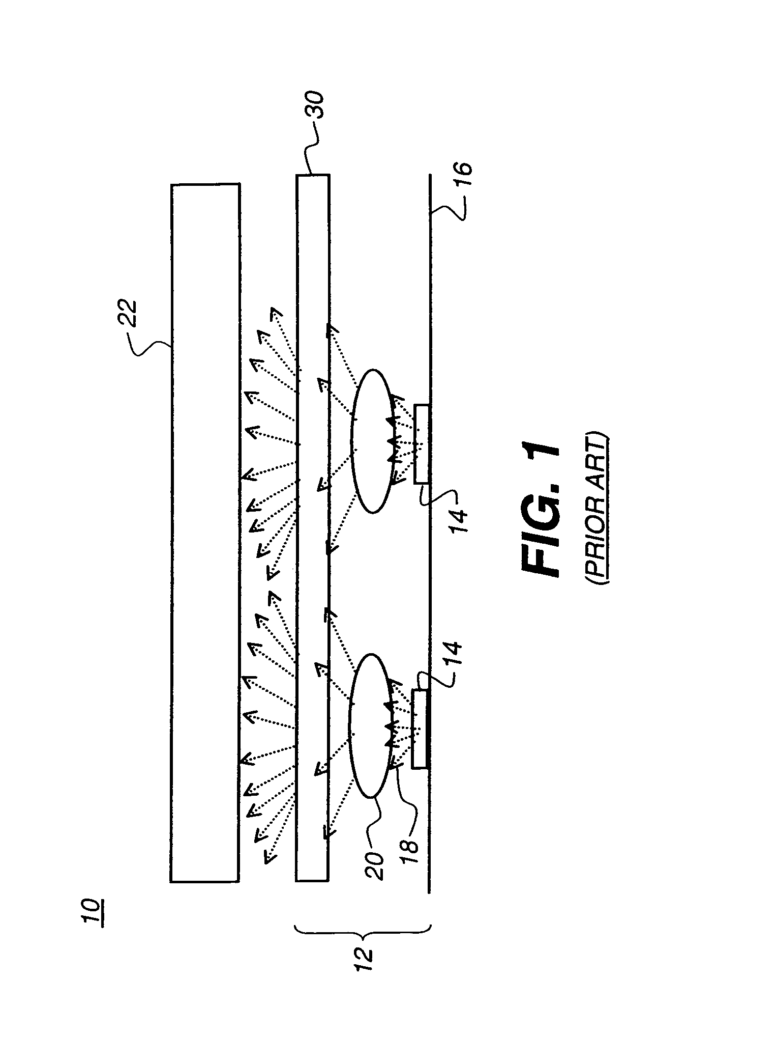
[0048]Referring to FIG. 1, there is shown, in simplified cross-sectional form for the sake of description, the arrangement of a portion of a conventional LCD display 10 using an LED backlight 12 to illuminate an LC device 22. A number of LEDs 14 are arranged along a surface 16, each providing a source illumination beam 18. A refractive element 20, typically a lens, spreads the source illumination beam. A diffuser 30 helps to provide further angular spread and minimize “hot spots” of higher luminance.

[0049]As a first approximation, LED 14 acts as a Lambertian source, or point source, broadcasting source illumination beam 18 over a broad range of angles. However, the spatial luminance distri...


PUM


Abstract

A lighting apparatus for providing illumination, comprising:a) an array of surface-emitting light sources, wherein each surface-emitting light source directs a source illumination beam, over a beam angle θ, toward an illumination plane;b) an array of beam spreading optical elements corresponding with the array of surface-emitting light sources, wherein refraction of the source illumination beam by each beam spreading optical element substantially satisfies a distribution function:dy / d⁢⁢θ=f⁡(θ)wherein y is a radial distance along the illumination plane from the optical axis of the beam-spreading optical element,dy is an arbitrarily small increment of the radial distance,dθ is the angular increment of the beam angle corresponding to dy, andƒ(θ) is the distribution function for the angular distribution of the light source, such that each beam spreading optical element adjusts the luminous intensity of the source illumination beam from the corresponding surface-emitting light source to provide a uniformized illumination beam directed toward the illumination plane;and,c) an array of beam-divergence reducing lens elements, wherein each beam-divergence reducing lens element reduces the angular divergence of a corresponding uniformized illumination beam,providing illumination having improved uniformity and reduced beam divergence thereby.

Description

FIELD OF THE INVENTION[0001]This invention generally relates to backlight illumination apparatus and more particularly relates to a backlight apparatus using an arrangement of light emitting diodes (LEDs).BACKGROUND OF THE INVENTION[0002]Transmissive Liquid Crystal Devices (LCDs) and other types of display devices require a backlight illumination source of some type. There are basically three illumination technologies in contention for the backlighting market: Electroluminescent Lamp (EL), Cold Cathode Fluorescent Lamp (CCFL), and Light Emitting Diode (LED). To date, CCFL technology has enjoyed the bulk of the laptop and portable display market, providing highly efficient and dependable light sources. CCFLs are particularly adaptable to edge-lit applications, in which these linear light sources direct light into one edge of a plate or film that spreads the light over its output surface. However, there are inherent drawbacks to CCFL technology that limit its projected growth. For exa...

Claims


Application Information

Patent Timeline
Patent Type & Authority Patents(United States)
IPC IPC(8): F21V5/00
CPCG02F1/133602G02F1/133603G02F1/133611G02F2001/133507G02F2001/133607G02F1/133507G02F1/133607G02F1/1335
Inventor LEE, JUNWONKESSLER, DAVIDMI, XIANG-DONG
Owner SKC HAAS DISPLAY FILMS CO LTD
Why Eureka
Try Eureka