Display device using vertical cavity laser arrays

a laser array and display device technology, applied in semiconductor lasers, active medium materials, instruments, etc., can solve the problems of limited contrast and color shift for large viewing angles, and achieve the enhancement of the color gamut of the liquid crystal display, the effect of reducing the divergence angle of outputted light, and enhancing the on-axis viewing brightness

Inactive Publication Date: 2007-08-28
EASTMAN KODAK CO
View PDF12 Cites 20 Cited by
  • Summary
  • Abstract
  • Description
  • Claims
  • Application Information

AI Technical Summary

Benefits of technology

[0022]It is an advantage of the present invention to use a pixelated two-dimensional microcavity device array as the light source for a liquid crystal display. Microcavity devices have the useful feature that through proper engineering of the device design it is possible to reduce the divergence angle of the outputted light to less than 10-15°. This small divergence angle enables a 1:1 correspondence between the microcavity's color elements and the liquid crystal display's color elements. Correspondingly, it is no longer necessary to include the color filter array as one of the LCD film components.
[0023]Since the microcavity light passes through the LC switches nearly on axis, the problems associated with contrast and color shifts for large viewing angles are limited. An additional feature of the near collimation of the light source is that the liquid crystal viewing angle compensation films can be removed from the display structure. It is also common to include collimating films as part of the LCD components; however, these films can be removed since the microcavity device output from the two-dimensional array is naturally collimated (<10-15° divergence angle).
[0024]Additional advantages of the present invention come from the light output from each color element being spectrally narrow. This property results in a large enhancement of the color gamut of the liquid crystal display. In applications that prefer a limited viewing angle, such as for privacy viewing, the near collimation of the light source results in a much enhanced on-axis viewing brightness for the display compared to typical ones. This enhancement can either permit greatly increased display brightnesses or can be traded for greatly increased display power efficiency (enabling a large boost in the battery lifetime).

Problems solved by technology

Since the microcavity light passes through the LC switches nearly on axis, the problems associated with contrast and color shifts for large viewing angles are limited.

Method used


Image

  • Display device using vertical cavity laser arrays
  • Display device using vertical cavity laser arrays
  • Display device using vertical cavity laser arrays

Examples


Embodiment Construction

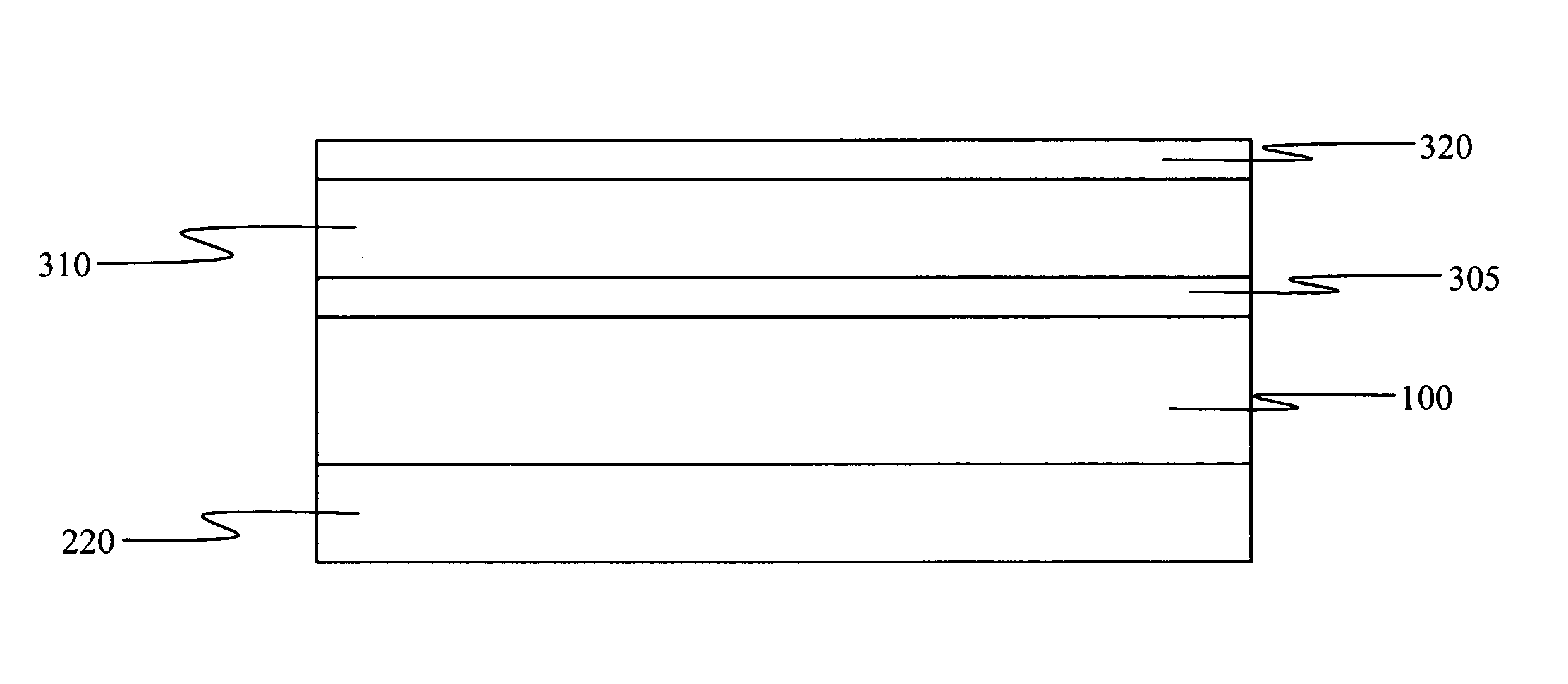
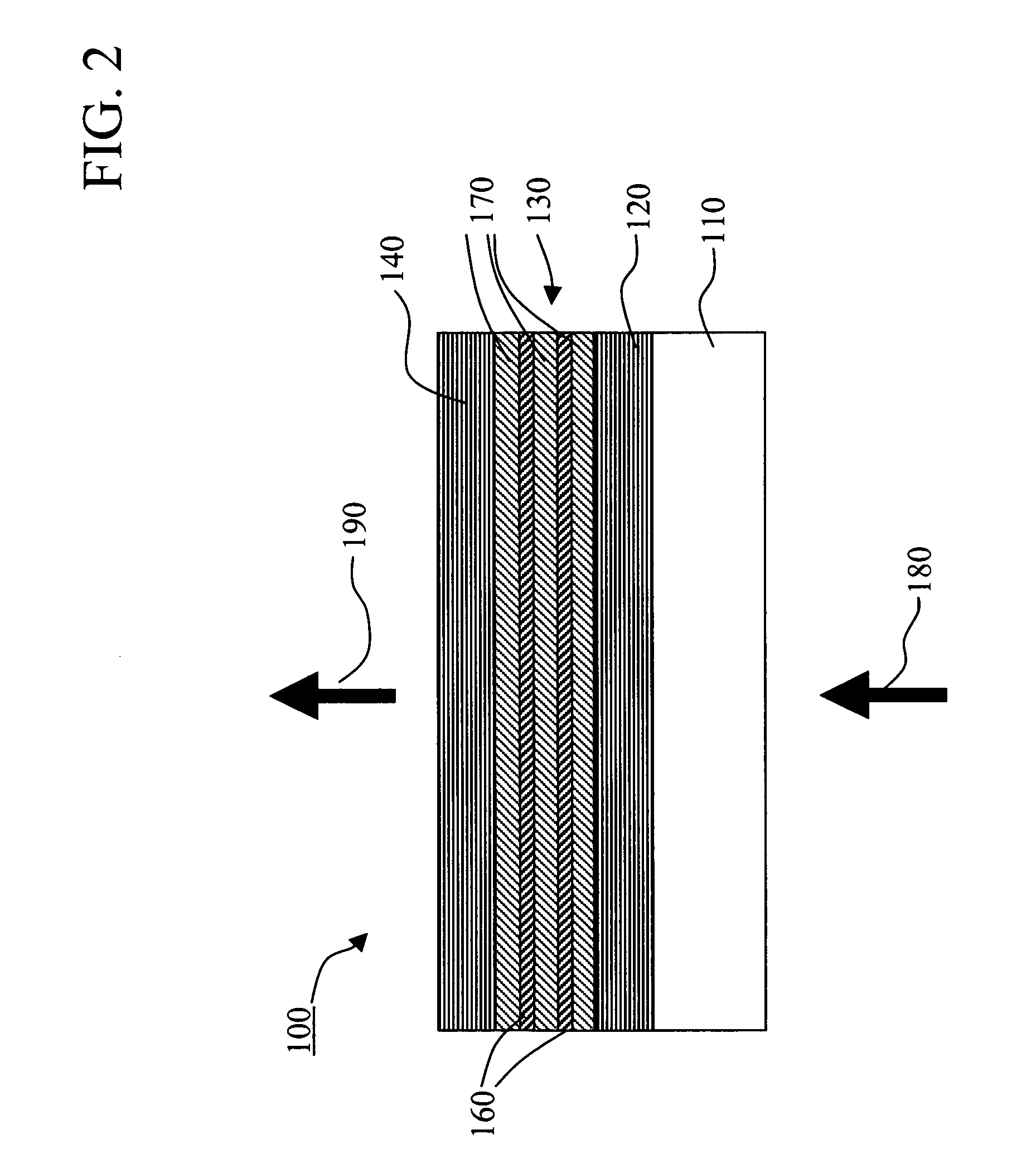
[0035]The invention is enabled by a light source that is both nearly collimated and spectrally narrow. In addition, the light source must contain red, green, and blue emitting elements from a common substrate whose size is on the scale of 80×240 μm. A light source that meets these criteria is a two-dimensional microcavity array device 100, as shown schematically in FIG. 2. FIG. 3 shows a top view of the microcavity array device 100 where on the surface of the microcavity device needs to be defined red, green, and blue (RGB) emitting elements 205. In order to produce red, green, and blue microcavity light from a common substrate, the active region 130 can be composed of organic-based gain media. In addition, recent research, R. N. Bhargava, Phys. Stat. Sol. 229, 897 (2002), points to the possibility of obtaining visible wavelength emission from inorganic-based nanoparticles. One possibility is ZnO nanoparticles (with preferred diameters less than 10 nm) either undoped or doped with i...


PUM

PropertyMeasurementUnit
divergence angleaaaaaaaaaa
sizeaaaaaaaaaa

Abstract

A display apparatus for producing colored pixelated light includes a backlight unit for providing a pump-beam light. The apparatus also includes a microcavity light-producing array responsive to pump-beam light and having pixels wherein each pixel including a transparent substrate, a bottom dielectric stack reflective to light over a predetermined range of wavelengths, an active region responsive to pump-beam light for producing display light, and a top dielectric stack spaced from the bottom dielectric stack and reflective to light over a predetermined range of wavelengths. The apparatus further includes a light shutter for permitting selected display light from the microcavity light-producing array to pass therethrough, a polarizing layer disposed between the microcavity light-producing array and the light shutter, and a beam expander disposed over the light shutter for increasing the angular cone of view of the display light.

Description

CROSS REFERENCE TO RELATED APPLICATIONS[0001]Reference is made to commonly assigned U.S. patent application Ser. No. 10 / 857,508 filed May 28, 2004 by Keith B. Kahen, et al., entitled “Display Device Using Vertical Cavity Laser Arrays”, and commonly assigned U.S. patent application Ser. No. 10 / 857,512 filed May 28, 2004 by Keith B. Kahen, et al., entitled “Vertical Cavity Laser Producing Different Color Light”, the disclosures of which are herein incorporated by reference.FIELD OF THE INVENTION[0002]The present invention relates to a display device for producing colored light which uses a microcavity device array.BACKGROUND OF THE INVENTION[0003]In order to facilitate reading of the specification, the following terms are defined. Optic axis herein refers to the direction in which propagating light does not see birefringence. Polarizer and analyzer herein refer to elements that polarize electromagnetic waves. However, the one closer to the source of the light will be called a polarize...

Claims


Application Information

Patent Timeline
Patent Type & Authority Patents(United States)
IPC IPC(8): G09G3/36C09K11/06G02F1/13357H01L51/30H01S5/183
CPCG02F1/133617G02F1/133621G02F2202/046
Inventor KAHEN, KEITH B.MONTBACH, ERICA N.
Owner EASTMAN KODAK CO
Why Eureka
Try Eureka