Vane platform rail configuration for reduced airfoil stress

a technology of airfoil stress and platform rail, which is applied in the direction of machines/engines, liquid fuel engines, lighting and heating apparatus, etc., to achieve the effects of reducing thermal deflection resistance, reducing thermally induced stresses, and improving component durability

Active Publication Date: 2007-06-12
ANSALDO ENERGIA SWITZERLAND AG
View PDF14 Cites 22 Cited by
  • Summary
  • Abstract
  • Description
  • Claims
  • Application Information

AI Technical Summary

Benefits of technology

[0007]It is an object of the present invention to provide a turbine vane assembly having reduced thermal stresses in the airfoil and platform regions.
[0008]It is another object of the present invention to provide a turbine vane assembly having increased flexibility along the inner platform region.

Problems solved by technology

The source of cracking in prior art vane assemblies related to the significant temperature differences over a short distance between the vane, platform, and inner rail, located along the inner platform, opposite to the airfoil.

Method used


Image

  • Vane platform rail configuration for reduced airfoil stress
  • Vane platform rail configuration for reduced airfoil stress
  • Vane platform rail configuration for reduced airfoil stress

Examples


Embodiment Construction

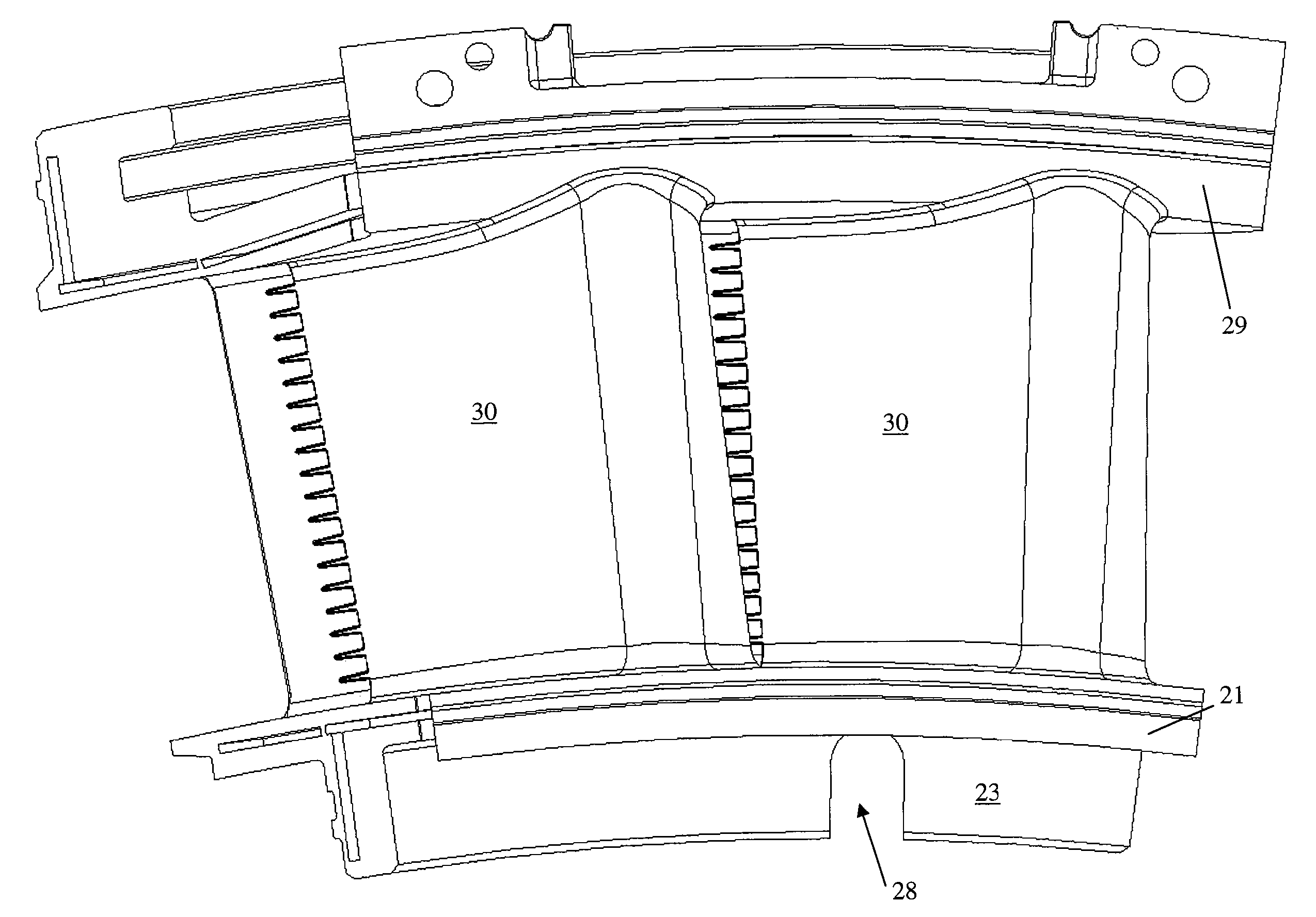
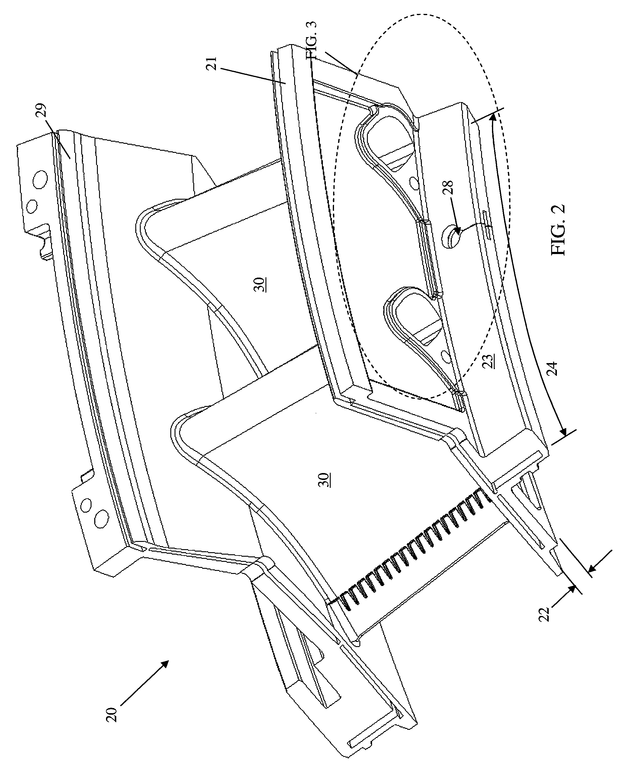
[0016]The present invention is shown in detail in FIGS. 2-6. Referring now to FIG. 2, a vane assembly for a gas turbine engine in accordance with the preferred embodiment of the present invention is shown. Vane assembly 20 comprises an inner arc-shaped platform 21 having a first thickness 22 and an inner rail 23 extending generally circumferentially along inner arc-shaped platform 21. Inner rail 23, which is shown in greater detail in FIGS.2-4, further comprises a rail length 24, a rail height 25, a rail thickness 26, an inner rail wall 27, and at least one opening 28 that extends from inner rail wall 27 and through rail thickness 26. The specific dimensions of rail length 24, rail height 25, and rail thickness 26 can vary depending on the turbine vane configuration and location in the engine. The vane assembly further comprises an outer arc-shaped platform 29 that is positioned radially outward of inner arc-shaped platform 21 and fixed to an airfoil 30 that extends from inner arc-s...


PUM


Abstract

A vane assembly for a gas turbine engine is disclosed having lower thermally induced stresses resulting in improved component durability. The stresses in the vane assembly airfoils are lowered by increasing the flexibility of the vane platform and reducing their resistance to thermal deflection. This is accomplished by placing an opening along the vane assembly rail that reduces the effective stiffness of the platform, thereby lowering the operating stresses in the airfoils of the vane assembly. A removable seal is then placed in the opening in order to prevent undesired leakages, while maintaining the benefit of the increased platform flexibility.

Description

TECHNICAL FIELD[0001]The present invention relates generally to gas turbine engines and more specifically to a turbine vane configuration having reduced airfoil stresses.BACKGROUND OF THE INVENTION[0002]A gas turbine engine typically comprises a multi-stage compressor, which compresses air drawn into the engine to a higher pressure and temperature. A majority of this air passes to the combustors, which mix the compressed heated air with fuel and contain the resulting reaction that generates the hot combustion gases. These gases then pass through a multi-stage turbine, which, in turn drives the compressor, before exiting the engine. A portion of the compressed air from the compressor bypasses the combustors and is used to cool the turbine blades and vanes that are continuously exposed to the hot gases of the combustors. In land-based gas turbines, the turbine is also coupled to a generator for generating electricity.[0003]Turbines are typically comprised of alternating rows of rotati...

Claims


Application Information

Patent Timeline
Patent Type & Authority Patents(United States)
IPC IPC(8): F01D9/04
CPCF01D9/041F05D2260/941
Inventor ELLIS, CHARLES A.PARKER, DAVIDSTROHL, J. PAGEMEDRANO, DAVID
Owner ANSALDO ENERGIA SWITZERLAND AG
Why Eureka
Try Eureka