Compressor airfoil surface wetting and icing detection system

a technology of airfoil surface and detection system, which is applied in the direction of ohmic resistance heating, electrical equipment, de-icing equipment, etc., can solve the problems of affecting and damaging other components of the compressor, such as blades and other vanes, time-consuming, labor-intensive and costly repairs

Inactive Publication Date: 2007-06-12
SIEMENS ENERGY INC
View PDF31 Cites 15 Cited by
  • Summary
  • Abstract
  • Description
  • Claims
  • Application Information

AI Technical Summary

Benefits of technology

[0009]The system can include a second thermocouple that is provided proximate the outermost surface so as to be electrically insulated from the heater. The second thermocouple can include a first thermocouple lead and a second thermocouple lead. A portion of the first lead can be electrically connected to a portion of the second lead to form a second thermocouple junction. The second thermocouple junction is located remotely from the heater so that the second thermocouple junction does not substantially sense heat generated by the heater. The second thermocouple can be operatively connected to the power source. Further, the second thermocouple can electrically connected in series and in opposing polarity to the first thermocouple. Such a dual thermocouple arrangement can minimizes any contribution to the thermocouple voltage reading that is attributable to non-heater sources.
[0019]When no ice or water is present on the outermost surface proximate at least one of the capacitors, the capacitance bridge circuit is substantially balanced. However, when water and / or ice is present on the outermost surface proximate at least one of the capacitors, the capacitance bridge circuit becomes unbalanced, thereby producing a voltage signal, which can alert an operator as to the presence of water and / or ice.

Problems solved by technology

If the ice dislodges from the vane during engine operation, the ice can impact and damage other components in the compressor, such as blades and other vanes.
Such damage can result in time-consuming, labor intensive and costly repairs.

Method used


Image

  • Compressor airfoil surface wetting and icing detection system
  • Compressor airfoil surface wetting and icing detection system
  • Compressor airfoil surface wetting and icing detection system

Examples


Embodiment Construction

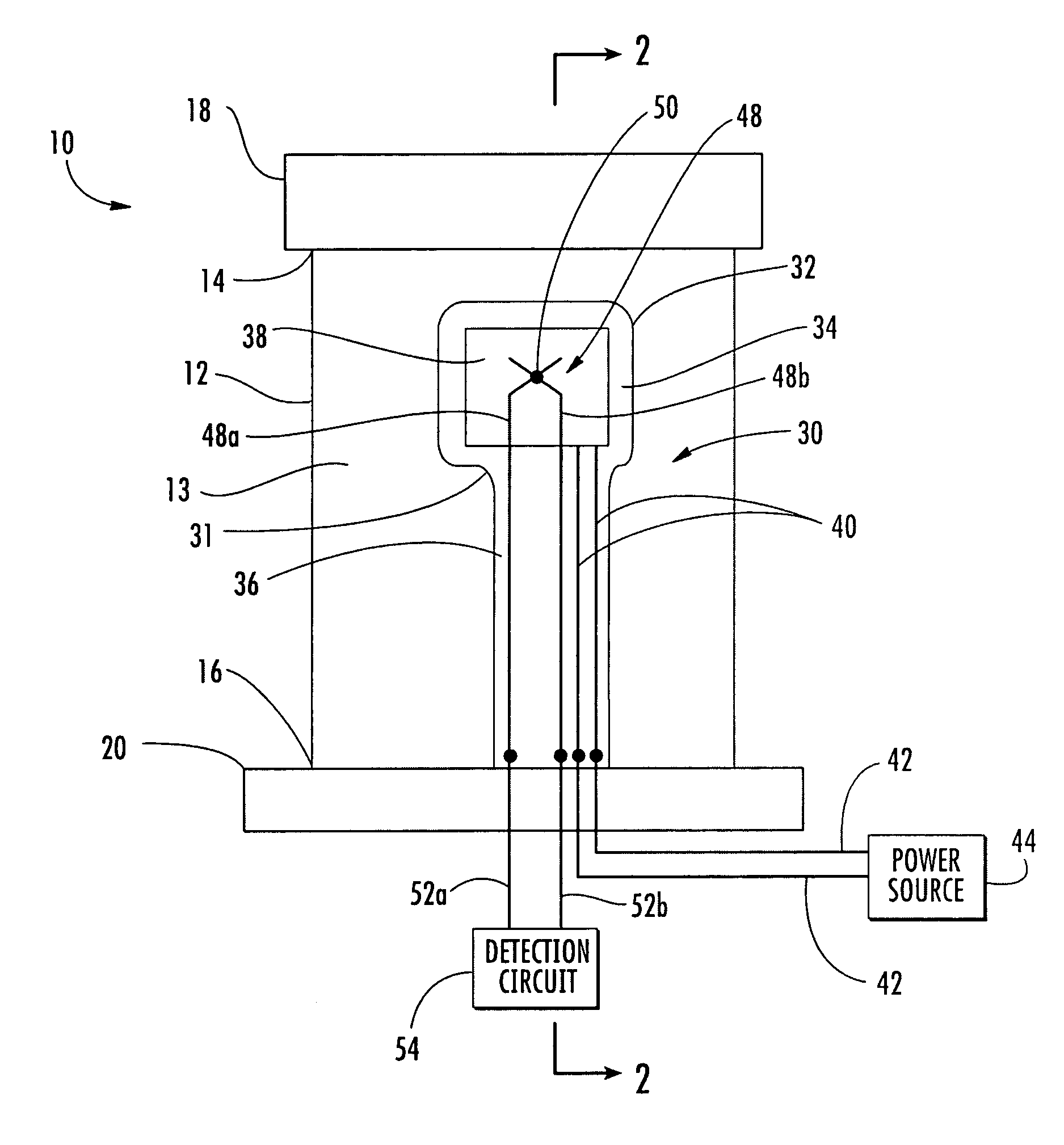
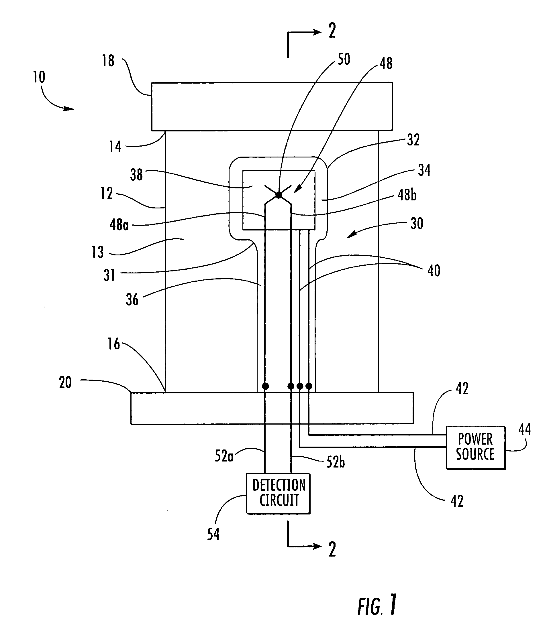
[0036]Embodiments of the present invention are directed to systems for detecting the presence ice or water on the surface of a compressor airfoil. In addition to detection, some of the systems according to aspects of the invention can be configured to facilitate removal of water and / or ice from the airfoil surface. Embodiments of the invention will be explained in the context of several possible systems, but the detailed description is intended only as exemplary. Embodiments of the invention are shown in FIGS. 1–13, but the present invention is not limited to the illustrated structure or application.

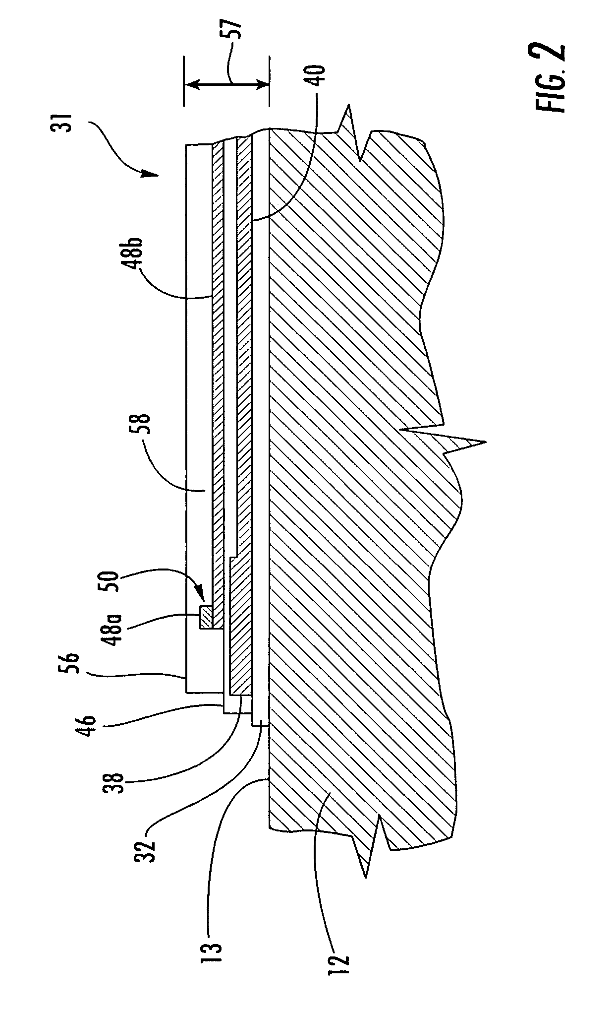
[0037]Aspects of the invention can be used in connection with various compressor components. Preferably, aspects of the invention are used in combination with a compressor vane. As shown in FIG. 1, a compressor vane 10 can include an elongated airfoil 12 that has an outer peripheral surface 13 as well as a radial inner end 14 and a radial outer end 16. The terms “radial inner” and “radia...


PUM


Abstract

In some instances, ice can form on the surface of a compressor airfoil. If the ice dislodges, it can impact and damage other compressor components. Aspects of the invention relate to systems for detecting the presence of ice or water on a compressor vane during engine operation. A ceramic insulating coating can be deposited on a portion of the surface of the vane. A heater and a thermocouple can be provided near the outermost surface of the coating such that the thermocouple can sense heat from the heater. The heater and the thermocouple can be provided within the coating. The presence of water film and / or ice on the coating surface can be detected by taking a thermocouple measurement following a heater pulse. The presence of a water film or ice results in a delay in the temperature rise detected by the thermocouple.

Description

FIELD OF THE INVENTION[0001]The invention relates in general to turbine engines and, more specifically, to the compressor section of a turbine engine.BACKGROUND OF THE INVENTION[0002]Under certain circumstances, ice can form inside of the compressor section of a turbine engine. Ice formation requires both adherence of moisture to a surface and a reduction in temperature. Water can enter a compressor in several ways. For example, water is sometimes injected into the compressor to increase power by wet compression. In some instances, the air drawn into the compressor may be moist because of the prevailing weather conditions (i.e., high humidity). As the air travels through the compressor, the moisture in the air can contact and adhere to various surfaces in the compressor, such as to a stationary vane.[0003]There are situations in which the temperature of the air in the compressor can drop to or below the freezing point of water. For instance, when the inlet guide vanes are closed bey...

Claims


Application Information

Patent Timeline
Patent Type & Authority Patents(United States)
IPC IPC(8): H05B1/00
CPCH05B1/0213
Inventor TWERDOCHLIB, MICHAEL
Owner SIEMENS ENERGY INC
Why Eureka
Try Eureka