On-DRAM termination resistance control circuit and method thereof

a resistance control circuit and resistance technology, applied in the direction of instruments, pulse techniques, baseband system details, etc., can solve the problems of inability to use resistance control circuits for resistance control of terminations, inability to match resistances properly, and errors in signal transmission, so as to minimize the area of resistance control circuits

Active Publication Date: 2007-06-12
SK HYNIX INC
View PDF6 Cites 46 Cited by
  • Summary
  • Abstract
  • Description
  • Claims
  • Application Information

AI Technical Summary

Benefits of technology

[0004]It is, therefore, an objective of the present invention to provide a resistance control circuit of an IC termination capable of contr

Problems solved by technology

When resistances are not matched properly, the transmitted signal may be reflected to cause errors in signal transmission.
However, if a fixed resistor is given externally for this matching, resistances cannot be matched properly due to decline of the IC, temperature change, or difference of manufacturing proc

Method used


Image

  • On-DRAM termination resistance control circuit and method thereof
  • On-DRAM termination resistance control circuit and method thereof
  • On-DRAM termination resistance control circuit and method thereof

Examples


Embodiment Construction

[0024]Hereinafter, with reference to the accompanying drawings, a preferred embodiment of the present invention will be explained in detail.

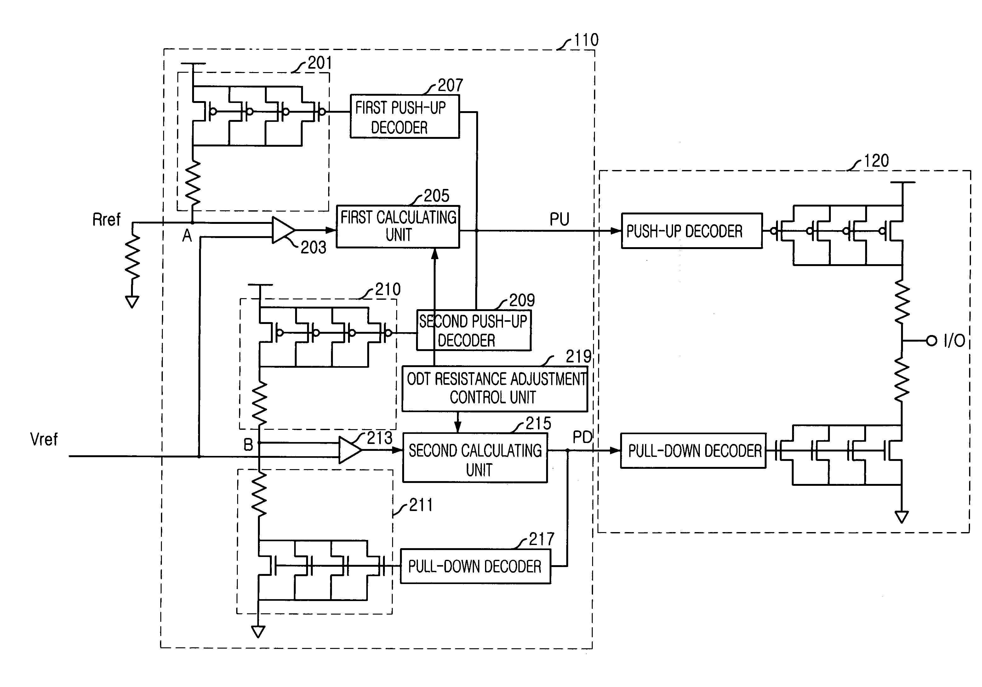
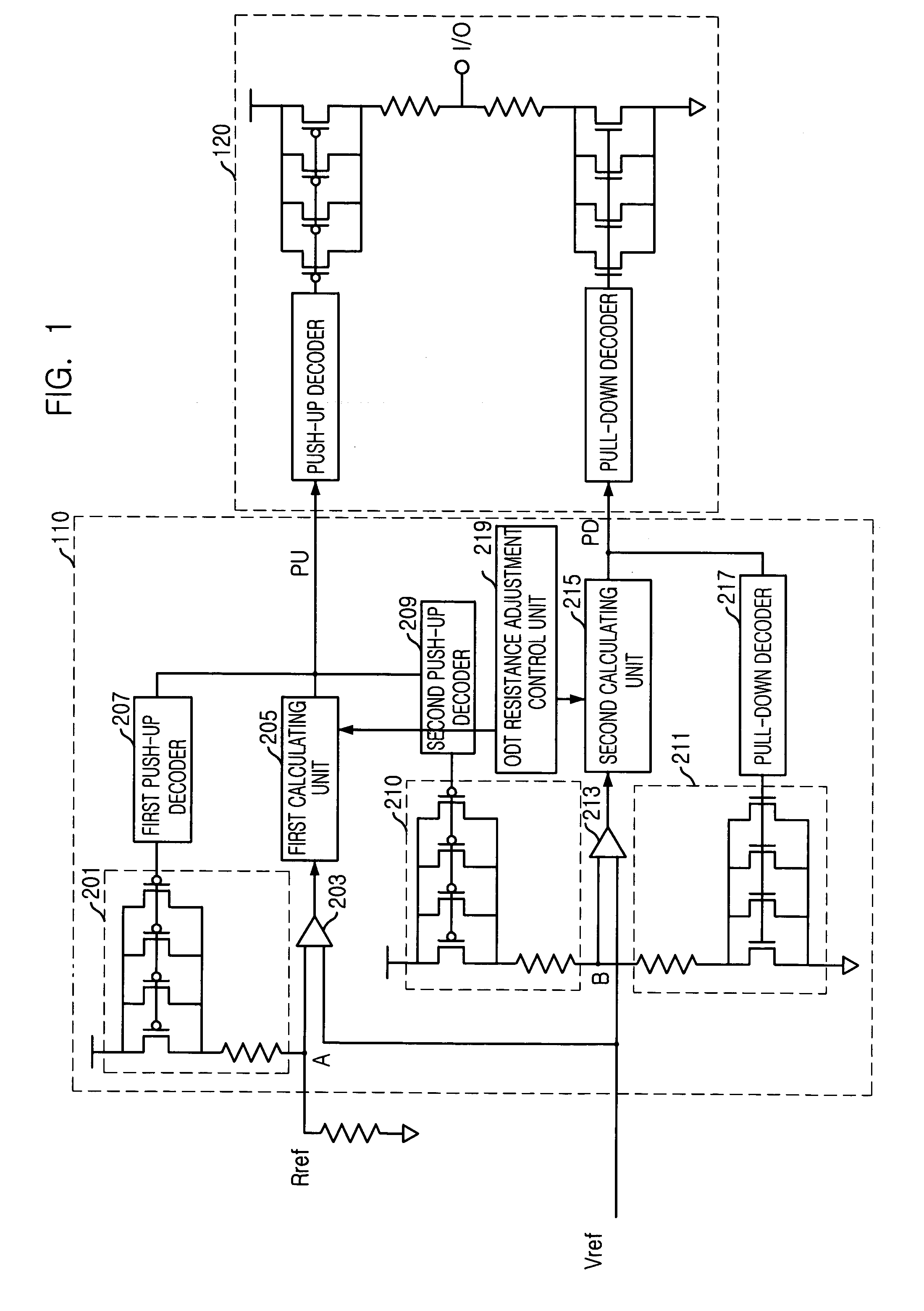
[0025]FIG. 1 provides an overall block diagram including an ODT (on-DRAM termination) resistance control circuit in accordance with the present invention.

[0026]The ODT resistance control circuit 110 according to the present invention is constructed to respectively provide a PU (push-up) code and a PD (pull-down) code to a push-up decoder and a pull-down decoder of an interface circuit 120 that performs the on-DRAM termination operation.

[0027]It will be described in detail for the operation of the ODT resistance control circuit 110 according to an embodiment of the present invention. It may be designed such that 4 of 8 parallel coupled transistors 201, 210, 211 (only 4 shown in FIG. 1) for forming an inner resistor are to be turned on when the ODT resistance control circuit 110 is enabled. At this point, when a first inner resistor 201 varies com...


PUM


Abstract

An on-DRAM termination resistance control circuit is capable of controlling resistance of an IC termination and minimizing area for the resistance control circuit by using a simplified circuit scheme. The on-DRAM termination resistance control circuit includes a push-up resistance adjusting unit, a pull-down resistance adjusting unit and resistance adjustment control unit. The push-up resistance adjusting unit adjusts resistances of a first and a second inner resistors based on an external reference resistor. The pull-down resistance adjusting unit adjusts a resistance of a third resistor based on the second inner resistor that is adjusted by adjustment of the push-up resistance control unit. The resistance adjustment control unit controls to alternatively repeat the operation of the push-up resistance adjusting unit and the pull-down resistance adjusting unit for a predetermined number of adjustment times.

Description

FIELD OF THE INVENTION [0001]The present invention relates to a resistance control circuit for an IC (Integrated Circuit) termination; and, more particularly, to a resistance control circuit for controlling resistance of an IC termination based on an externally coupled resistor.BACKGROUND OF THE INVENTION [0002]Generally, a resistor of an IC termination is needed to make signal transmission between devices smooth. When resistances are not matched properly, the transmitted signal may be reflected to cause errors in signal transmission. However, if a fixed resistor is given externally for this matching, resistances cannot be matched properly due to decline of the IC, temperature change, or difference of manufacturing process. For this, a new technique is introduced for controlling the resistance of the IC termination by controlling the number of turned-on transistors among transistors, which are coupled in parallel, to have same resistance as an external reference resistor.[0003]U.S. ...

Claims


Application Information

Patent Timeline
IPC IPC(8): H03K17/16G11C7/10H04L25/02
CPCH04L25/0278G11C7/10
Inventor CHOE, SEONG-MIN
Owner SK HYNIX INC
Why Eureka
Try Eureka