Clock diagnostics

a clock and timekeeping technology, applied in the direction of testing circuits, instruments, horology, etc., can solve the problems of not having the benefit of microprocessor technology in older systems, no tools available to address the need for on-location diagnostics, and no automatic or semi-automatic diagnostic electronics for performing a plurality of diagnostic self-tests at the secondary clock

Active Publication Date: 2007-06-12
SAPLING
View PDF5 Cites 60 Cited by
  • Summary
  • Abstract
  • Description
  • Claims
  • Application Information

AI Technical Summary

Benefits of technology

[0036]whereby the processing unit is further configured to initiate and perform a diagnostic test to determine the operability of the memory upon activation of a control device, and to display a result of the diagnostic test via a display device at the slave clock.
[0037]In another embodiment, the invention comprises a system and method in which at least three different series of diagnostic tests may be initiated by an operator at either a slave clock or a master clock, each series being selected by activating a control device a predetermined number of times within a predetermined time interval.
[0038]In another embodiment, the invention comprises a system and method for initiating and executing a plurality of diagnostic tests on com

Problems solved by technology

Older systems did not have the benefit of microprocessor technology, as do units produced today.
Some prior art clock systems have also shown simple means in the master clock that is limited to forcing secondary clock hands to a known position.
However, no automatic or semi-automatic diagnostic electronics for performing a plurality of diagnostic self-tests at the secondary clock is known to be included in secondary clocks as described

Method used


Image

  • Clock diagnostics
  • Clock diagnostics
  • Clock diagnostics

Examples


Embodiment Construction

Summary of Features

[0052]Some of the significant features of a preferred embodiment of the present invention may be summarized as follows:

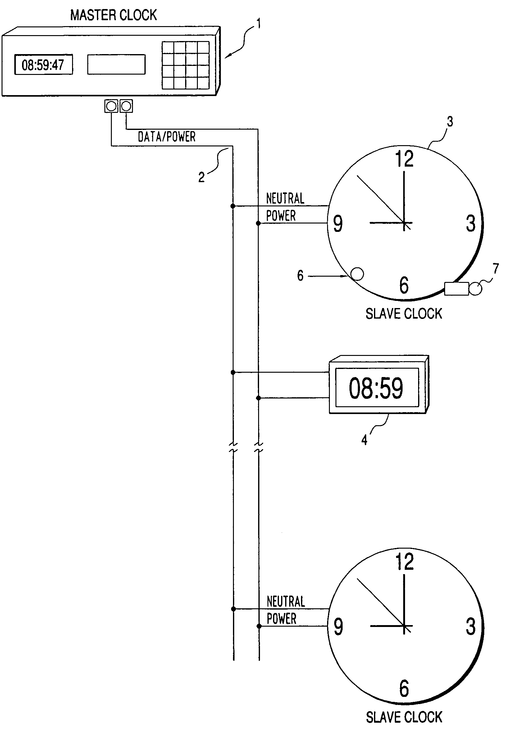
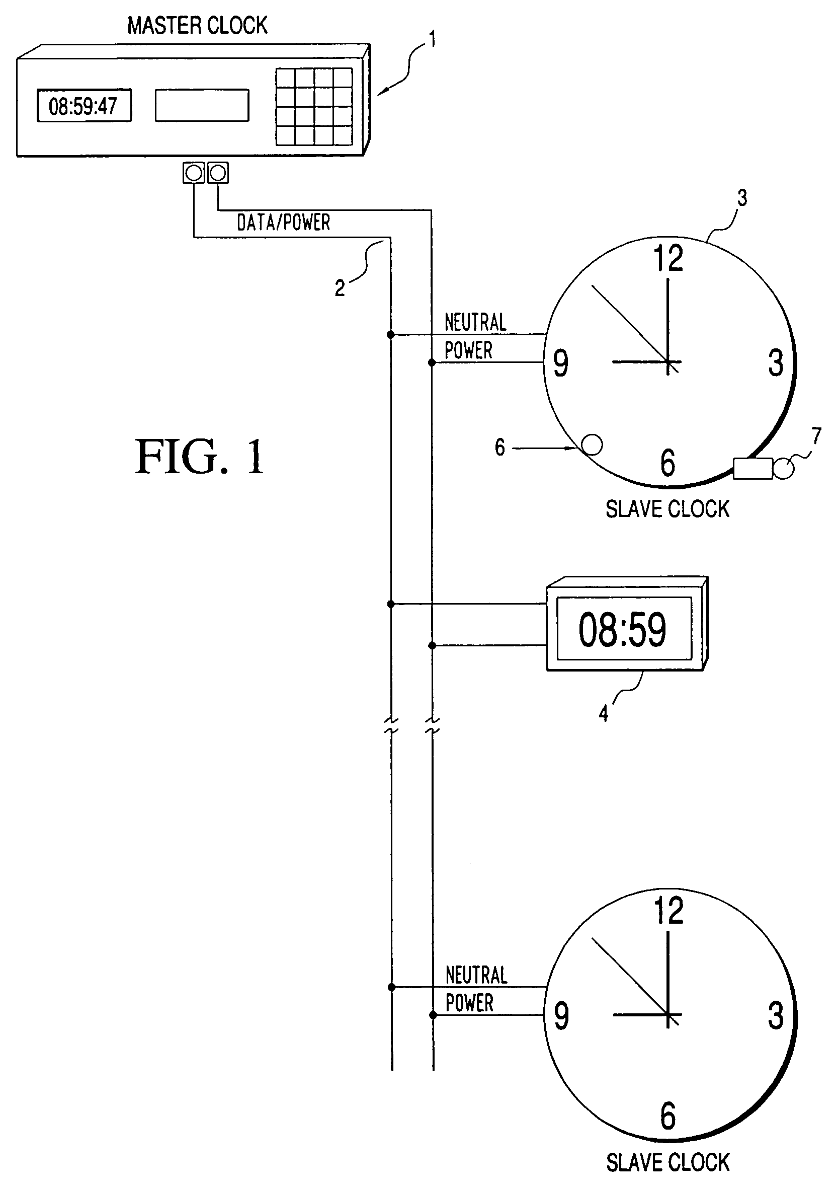
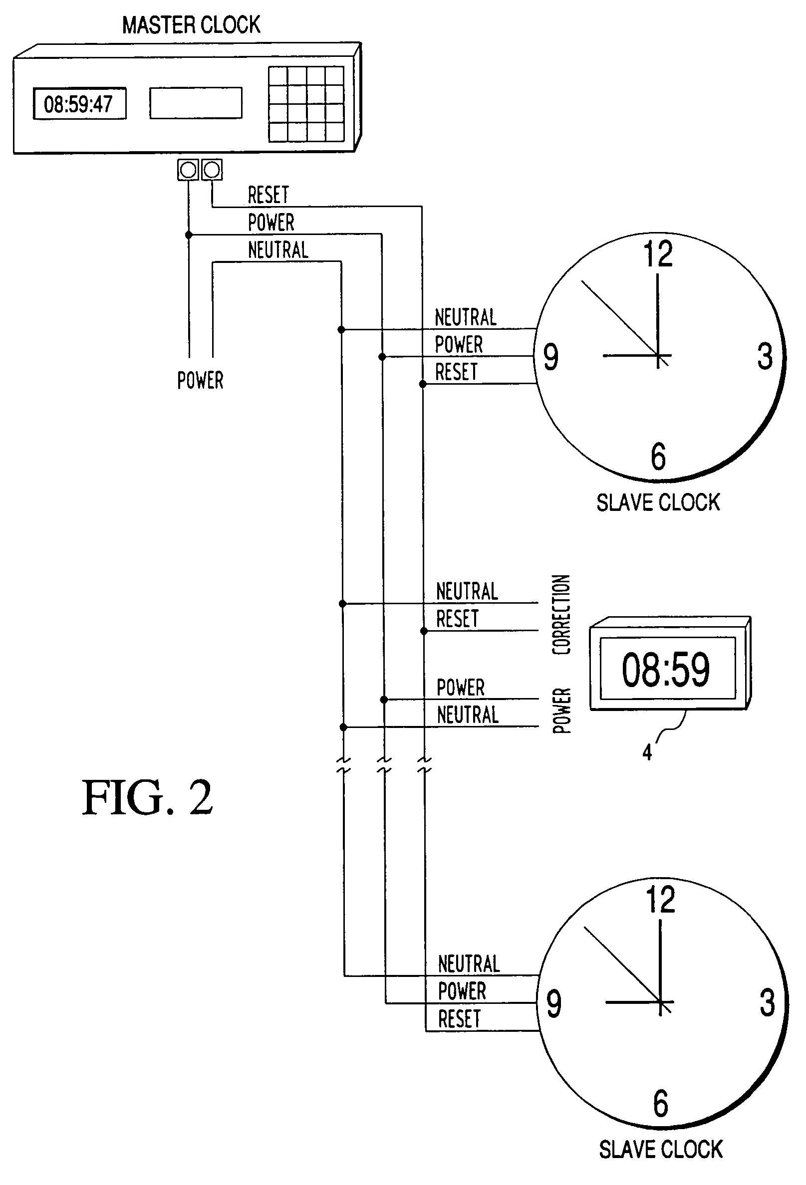
[0053]First, the secondary or “slave” clocks of a timekeeping system (see FIGS. 1 and 2) include the diagnostic capability to display via a visual or other indicator, such as an LED display or hand position, the current status of the secondary clock with regard to communication protocol type, ability to receive data, and indicate normal / abnormal internal clock functions. In a preferred embodiment, the number, duration and color of light flashes from the LED indicates the type of problem or other condition detected.

[0054]Second, the secondary clocks include the diagnostic capability to initiate one or more self-tests via a pushbutton or other operator-activated device on the secondary clock body.

[0055]Third, the secondary clocks include a capability to receive commands from a remote location (e.g., a master clock) to perform self-diagnostics. This ...


PUM


Abstract

Disclosed is a clock for use in a master/slave clock system, including a system and method for semi-automatically performing diagnostic self-tests on the status and operability of a plurality of components of one or more secondary clocks. The invention addresses a multitude of diagnostic and problem detection issues, including “no fault found.”

Description

CROSS-REFERENCE TO RELATED APPLICATION[0001]This application is entitled to the benefit of U.S. Provisional Patent Application Ser. No. 60 / 438,049, filed Jan. 3, 2003. Such application is incorporated herein by reference.FEDERALLY SPONSORED RESEARCH[0002]Not ApplicableSEQUENCE LISTING OR PROGRAM[0003]Not ApplicableBACKGROUND OF THE INVENTION[0004]The present invention pertains to diagnostic systems for timekeeping systems, and more particularly to diagnostic systems for master / slave clock systems, commonly used in schools, hospitals, offices and industrial applications.[0005]Many timekeeping systems are comprised of a master clock driving or communicating with one or more “slave” or secondary clocks that are periodically updated to be time synchronous to the master. Older systems did not have the benefit of microprocessor technology, as do units produced today. In modern systems, both the master and secondary clocks frequently contain microprocessors, and it is advantageous to utili...

Claims


Application Information

Patent Timeline
IPC IPC(8): G04C13/08G04C13/02G06F19/00
CPCG04C13/022
Inventor SHEMESH, ILAN
Owner SAPLING
Why Eureka
Try Eureka