
Automatic tank cleaning system

a tank cleaning and automatic technology, applied in the direction of multi-stage water/sewage treatment, waste water treatment from quaries, separation processes, etc., can solve the problems of difficult removal of settled entrained solid difficult screening of entrained solids, and difficult removal of settled solids from the bottom of the tank

Active Publication Date: 2007-06-19
MI
View PDF1 Cites 18 Cited by
  • Summary
  • Abstract
  • Description
  • Claims
  • Application Information

AI Technical Summary

Benefits of technology

The system efficiently recycles water, reduces waste, and minimizes confined space entry, allowing for faster, safer, and more efficient cleaning of tank interiors with reduced labor and operational costs.

Problems solved by technology

Unlike drill cuttings, these entrained solids are difficult to remove by screening.
However, upon standing, the solids often settle out over long periods of time (i.e. hours to days).
Removal of the settled entrained solids from the bottom of a tank has proven to be a difficult problem.
Such operations are both time and labor intensive and involve placing people inside of large storage tanks which raises certain safety concerns.
However, such tanks are expensive and an inefficient use of space on an offshore drilling rig or drilling rig service boat.

Method used


Image

  • Automatic tank cleaning system
  • Automatic tank cleaning system
  • Automatic tank cleaning system

Examples


Embodiment Construction

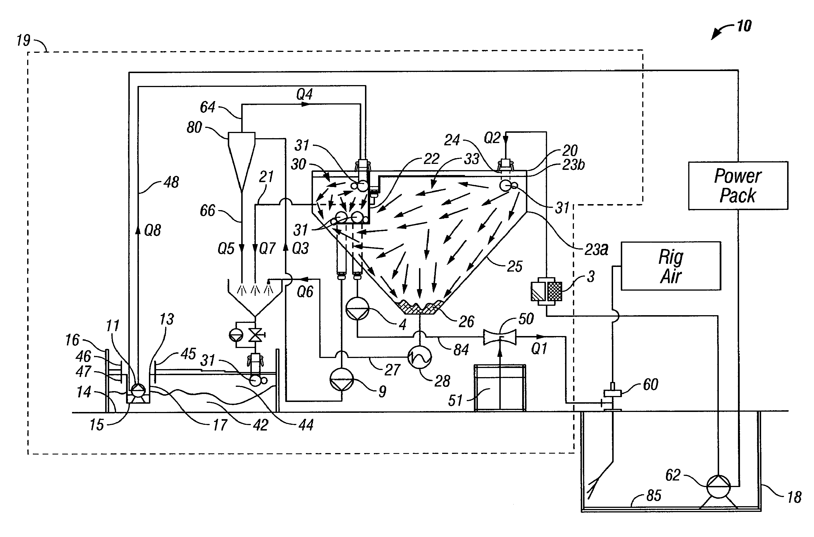
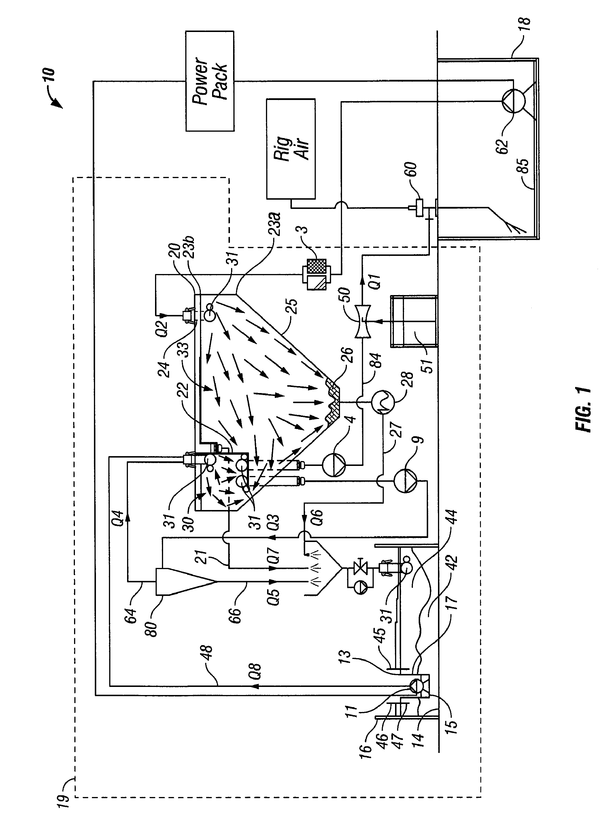
[0013]The above illustrative embodiment will be better understood with reference to FIG. 1 in which the tank cleaning system 10 is schematically shown. One of skill in the art should appreciate that the schematic utilizes generally accepted representations of pumps, etc., which should be well known.

[0014]Turning now to FIG. 1, the tank cleaning system 10 includes a water recycling unit 19 and one or more rotary jet head washers 60. Discussion of the components of this closed system will begin with the rotary jet head washers 60.

[0015]Referring to FIG. 3, one or more of the rotary jet head washers 60 are positioned within the mud tank 18. Although shown as being fixed in position, these multi headed or single-headed nozzle rotary jet heads 60 may be lowered into the tank 18 or otherwise suspended and positioned temporarily or permanently within the tank 18 using brackets 83, stands, penetration through the deck / side of the tank or the like. The rotary jet heads 60 are supplied with p...


PUM

PropertyMeasurementUnit
pressureaaaaaaaaaa
timeaaaaaaaaaa
currentaaaaaaaaaa

Abstract

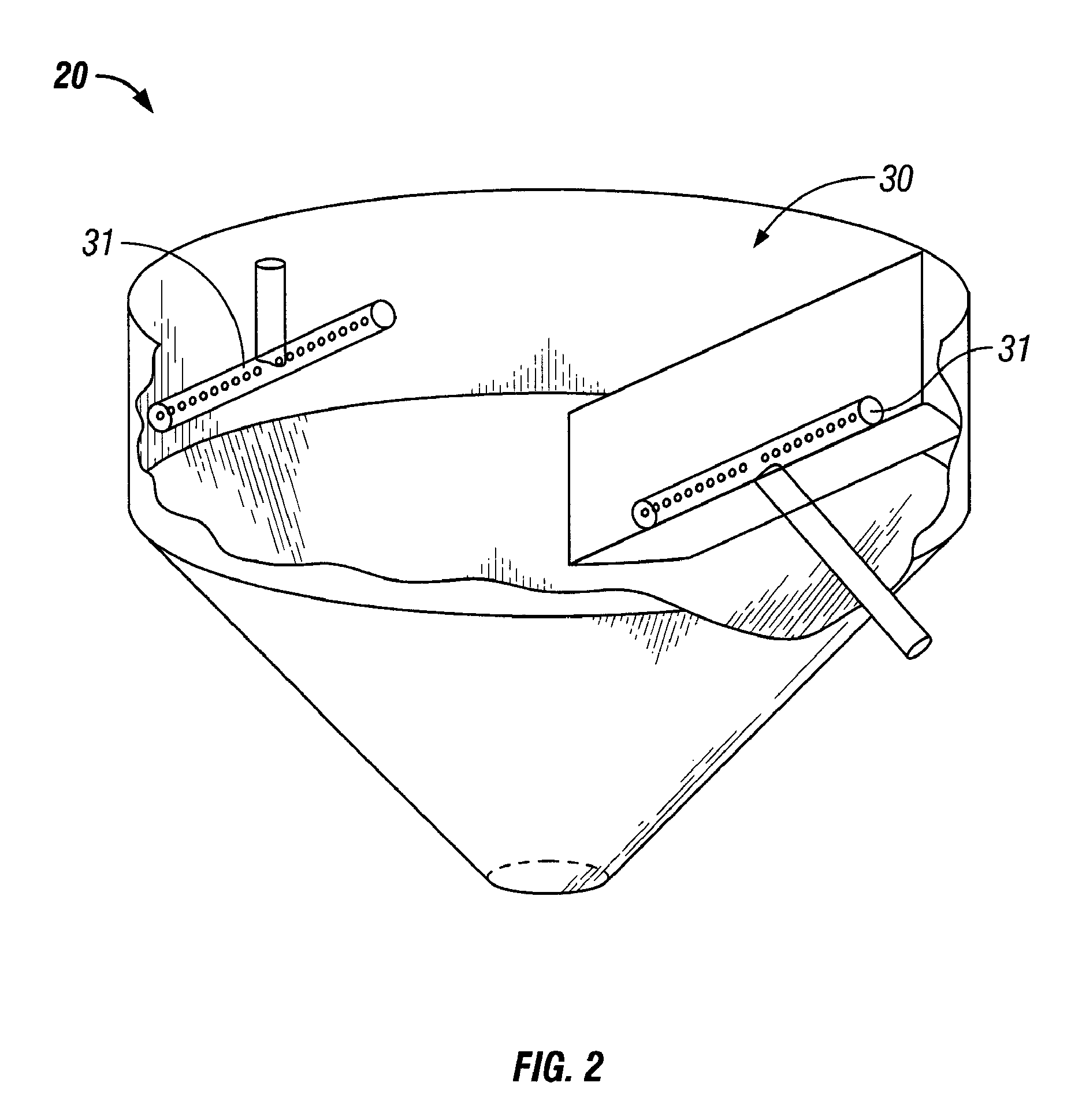
An automatic tank cleaning system includes a water recycling unit having a weir therein and a conically-shaped bottom, a cutting box having a portable weir therein, a hydrocyclonic separator, and a mud tank. Tank slop is pumped from the mud tank to the water recycling unit where solids collect at the bottom. The solids are removed and collected in the cutting box. Water in the recycling unit may be pumped through the hydrocyclonic separator. Solids removed by the separator are collected in the cutting box and the water is directed into a clean water compartment defined by the weir within the recycling unit. Water in the cutting box is collected by the portable weir therein and pumped to the clean water compartment. Water from the clean water compartment is pumped to one or more rotary jet heads within the mud tank. Overflow from the water recycling unit may be directed to the cutting box. A chemical inductor may be used to add cleaning chemicals to the water prior to being directed through the wash nozzle. Turbulence preventers may be included at the inlet of each flow line to prevent turbulence from occurring in the tank to which the fluid is directed.

Description

[0001]This application claims the benefit of U.S. Provisional Application No. 60 / 554,557, filed Mar. 19, 2004 and entitled, “Automatic Tank Washing Apparatus and Method of Use”; U.S. Provisional Application No. 60 / 565,303, filed Apr. 26, 2004 and entitled, “Automatic Tank Washing Apparatus and Method of Use”; U.S. Provisional Application No. 60 / 620,377, filed Oct. 20, 2004 and entitled, “Automatic Tank Cleaning System”; and U.S. Provisional Application No. 60 / 633,766, filed Dec. 7, 2004 and entitled, “Automatic Tank Cleaning System,” the contents each of which are incorporated herein by reference. New matter has been added to this application for which priority is not claimed.BACKGROUND OF INVENTION[0002]Rotary drilling methods employing a drill bit and drill stems have long been used to drill wellbores in subterranean formations. Drilling fluids or muds are commonly circulated in the well during such drilling to cool and lubricate the drilling apparatus, lift cuttings out of the we...

Claims


Application Information

Patent Timeline
Patent Type & Authority Patents(United States)
IPC IPC(8): B01D21/00B01D21/26B08B9/08C02F1/00C02F1/38B08B9/093
CPCB01D21/0006B01D21/0042B01D21/02B01D21/2416B01D21/245B01D21/2488B08B9/093B08B9/0933B01D21/267B01D2221/08C02F1/38C02F2103/10
Inventor ERIKSEN, FRANK
Owner MI
Learn More