Active ripple reduction switched mode power supplies

a power supply and switching mode technology, applied in the field of switching mode power supplies, can solve the problems of communication interference with other electronic devices, interfering with other electronic devices such as computers or televisions, and various communication protocols used by mobile terminals, and achieve the effects of reducing or eliminating active reducing ripple in supply voltage, and reducing or eliminating ripple voltag

Active Publication Date: 2007-06-19
QORVO US INC
View PDF11 Cites 151 Cited by
  • Summary
  • Abstract
  • Description
  • Claims
  • Application Information

AI Technical Summary

Benefits of technology

[0009]The present invention provides a system and method for actively reducing ripple in a supply voltage provided by a switched mode power supply. In general, active ripple reduction circuitry operates to sense the ripple in the supply voltage to provide a signal indicative of the ripple. The signal indicative of the ripple is inverted and provided to the output of the switched mode power supply to substantially reduce or eliminate the ripple in the supply voltage.
[0010]In one embodiment, the active ripple reduction circuitry high-pass filters the supply voltage to provide a signal indicative of the ripple voltage. The signal indicative of the ripple voltage is amplified and inverted to provide a ripple reduction signal. The ripple reduction signal is provided to the output of the switched mode power supply to substantially reduce or eliminate the ripple voltage.
[0011]In another embodiment, the switched mode power supply includes a converter control system and an inductor coupled between an output of the converter control system and the output of the switched mode power supply. The active ripple reduction circuitry includes integration circuitry that integrates a voltage across the inductor to provide a signal indicative of the ripple current. The signal indicative of the ripple current is converted from a voltage to a current by a voltage-to-current converter to provide a ripple reduction signal. The ripple reduction signal is provided to the output of the switched mode power supply to substantially reduce or eliminate the ripple current.

Problems solved by technology

An unfortunate side effect of the convenience of this wireless communication is that the signal-carrying electromagnetic radiation that forms the backbone of the communication may interfere with other electronic devices.
While interfering with other electronic devices like a computer or television is problematic, it is also possible for multiple mobile terminals operating in proximity to one another to have cross channel EMI.
On top of the FCC emissions rules, the various communication protocols used by mobile terminals may impose more restrictive limitations with specific attention paid to side band transmission levels.
If the DC—DC converter is used to provide a supply voltage (Vcc) to a saturated power amplifier, this ripple may mix with the radio frequency carrier to generate spurious side band signals.
This substitution avoids the ripple issues, but does so at the expense of decreased efficiency and shorter battery life.
However, the large inductors and capacitors are physically large and require a significant amount of die area.
In addition, large inductors and capacitors are more expensive and result in a low Unity Gain Bandwidth (UGBW).
The low UGBW makes polar modulation impossible and may cause turn-on mask problems.
However, running the power amplifier linearly significantly reduces the efficiency of the power amplifier and negates the efficiency of the switched mode power supply.
However, each phase requires a separate inductor, thereby adding cost and size.

Method used


Image

  • Active ripple reduction switched mode power supplies
  • Active ripple reduction switched mode power supplies
  • Active ripple reduction switched mode power supplies

Examples


Embodiment Construction

[0018]The embodiments set forth below represent the necessary information to enable those skilled in the art to practice the invention and illustrate the best mode of practicing the invention. Upon reading the following description in light of the accompanying drawing figures, those skilled in the art will understand the concepts of the invention and will recognize applications of these concepts not particularly addressed herein. It should be understood that these concepts and applications fall within the scope of the disclosure and the accompanying claims.

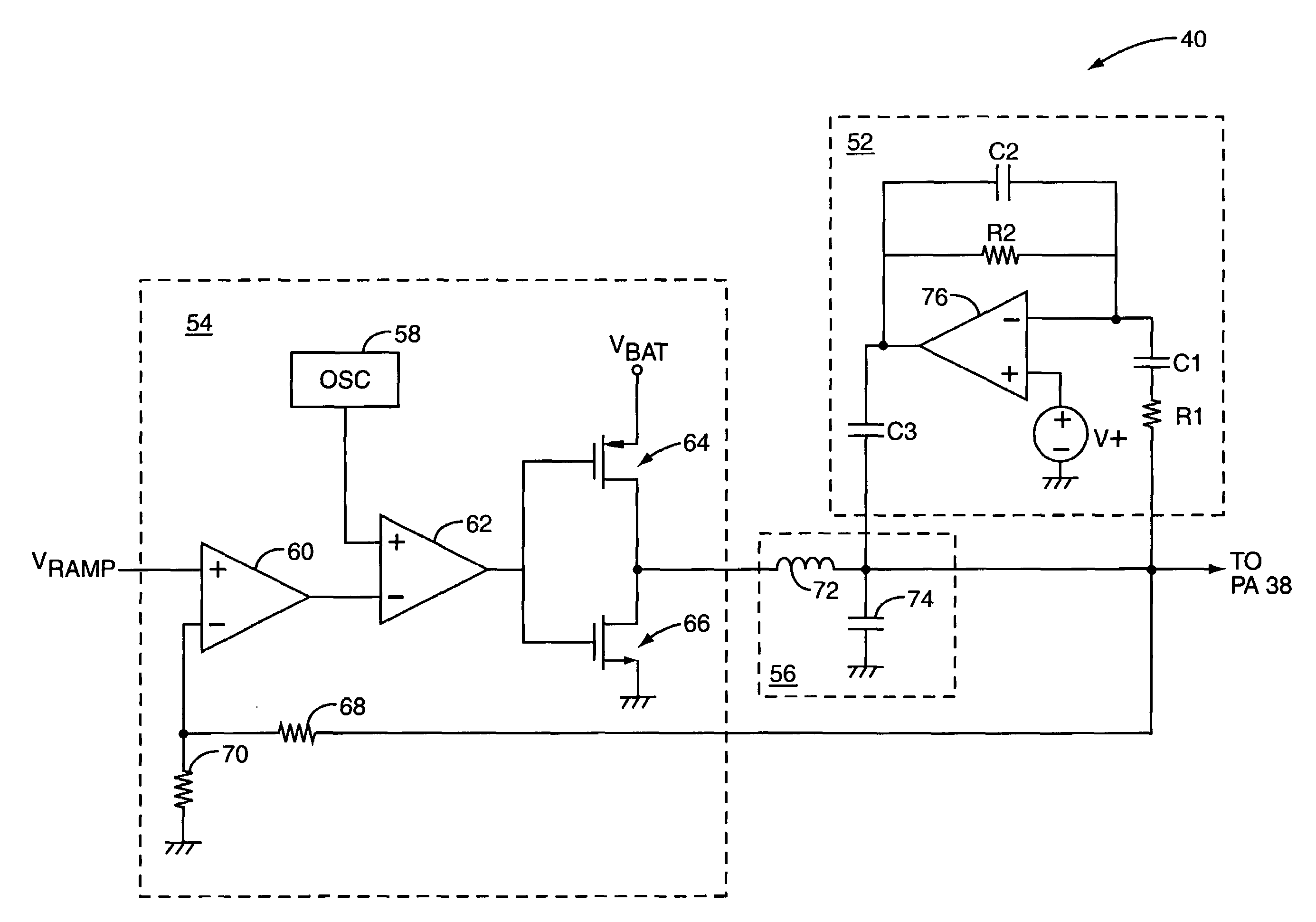
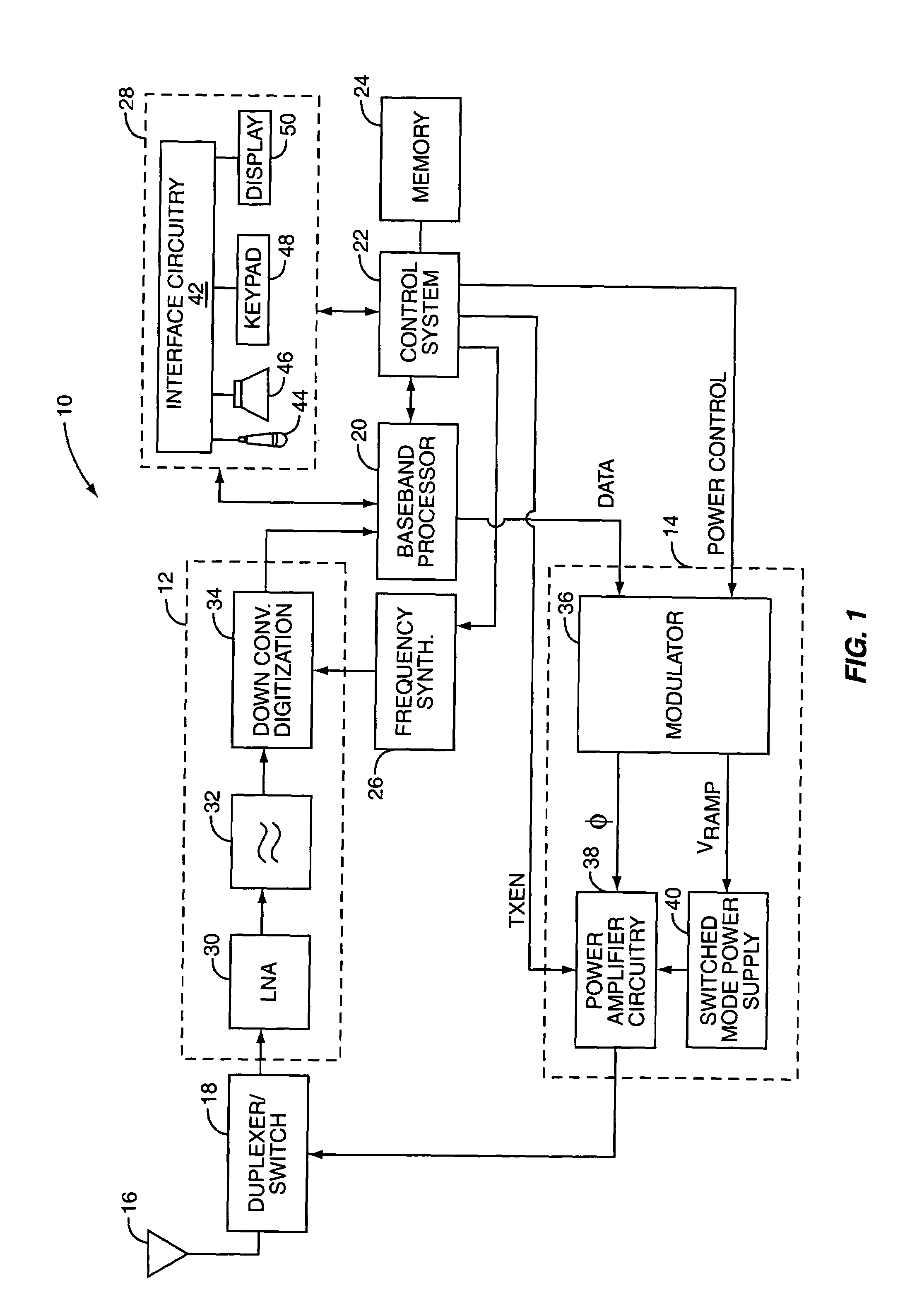
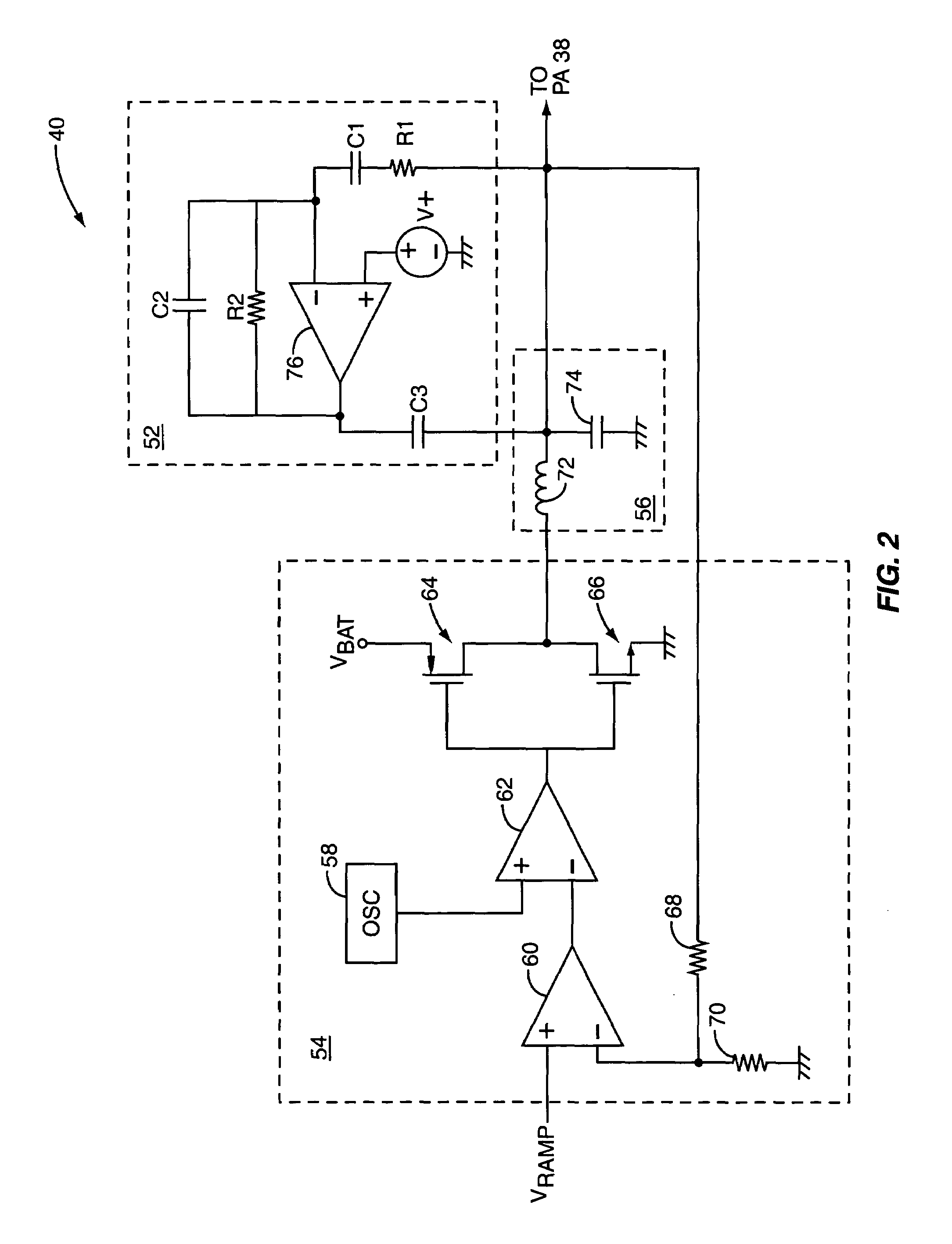
[0019]The present invention is preferably incorporated in a mobile terminal 10, such as a mobile telephone, personal digital assistant, wireless Local Area Network (LAN) device, a base station in a mobile network, or the like. The basic architecture of a mobile terminal 10 is represented in FIG. 1, and may include a receiver front end 12, a radio frequency transmitter section 14, an antenna 16, a duplexer or switch 18, a baseband ...


PUM


Abstract

A system and method are provided for actively reducing ripple in a supply voltage provided by a switched mode power supply. In general, active ripple reduction circuitry operates to sense the ripple in the supply voltage to provide a signal indicative of the ripple. The signal indicative of the ripple is inverted and provided to the output of the switched mode power supply to substantially reduce or eliminate the ripple in the supply voltage.

Description

FIELD OF THE INVENTION[0001]The present invention relates to switched mode power supplies and more specifically relates to a system for actively reducing a ripple in the output of a switched mode power supply.BACKGROUND OF THE INVENTION[0002]Mobile terminals such as cellular phones have become ubiquitous in modern society. Mobile terminals rely on sending an electromagnetic signal through the air to a base station and receiving electromagnetic signals through the air from the base station. An unfortunate side effect of the convenience of this wireless communication is that the signal-carrying electromagnetic radiation that forms the backbone of the communication may interfere with other electronic devices. This phenomenon is known as electromagnetic interference (EMI) or electromagnetic compatibility (EMC).[0003]While interfering with other electronic devices like a computer or television is problematic, it is also possible for multiple mobile terminals operating in proximity to one...

Claims


Application Information

Patent Timeline
Patent Type & Authority Patents(United States)
IPC IPC(8): G05F1/00G05F1/573
CPCH02M1/143
Inventor KAY, MICHAEL R.
Owner QORVO US INC
Why Eureka
Try Eureka