Circuit and method for implementing a multi-function pin on a PWM controller chip in a voltage converter

a voltage converter and multi-function technology, applied in the direction of electric variable regulation, process and machine control, instruments, etc., can solve the problems of increasing circuit cost and complexity, reduce the number of pins of the pwm controller chip, reduce the cost and complexity of the circuit, and increase the noise immunity of the signal detection

Active Publication Date: 2007-06-19
RICHTEK TECH
View PDF1 Cites 46 Cited by
  • Summary
  • Abstract
  • Description
  • Claims
  • Application Information

AI Technical Summary

Benefits of technology

[0006]Another object of the present invention is to provide a low cost, simple, and reduced pin counts PWM controller chip for a voltage converter.
[0008]Since the enable function, power sensing function, and over-current protection function are accomplished by using only a multi-function pin, the pin counts of a PWM controller chip are reduced. Moreover, the multi-function pin is connected to the phase node, and therefore the power sensing arrangement and over-current protection arrangement may use low voltage elements for implementing their circuits to reduce the cost and complexity of the circuits. Further, a conventional voltage converter carries out the voltage detection for the over-current protection during the high side switch turns on, while a voltage converter of the present invention carries out the voltage detection for the over-current protection during the low side switch turns on. Generally, in a voltage converter, the duty of a high side switch is smaller than the duty of a low side switch, and therefore a voltage converter of the present invention has a longer time period for the over-current protection arrangement to detect the voltage on the multi-function pin, thereby increasing the noise immunity in the signal detection.

Problems solved by technology

Moreover, the pin OCSET is connected to the converter power Vin through the sense resistor RS, which requires the power sensing arrangement and over-current protection arrangement to use high voltage elements for implementing their circuits, thereby increasing the cost and complexity of the circuits.

Method used


Image

  • Circuit and method for implementing a multi-function pin on a PWM controller chip in a voltage converter
  • Circuit and method for implementing a multi-function pin on a PWM controller chip in a voltage converter
  • Circuit and method for implementing a multi-function pin on a PWM controller chip in a voltage converter

Examples


Embodiment Construction

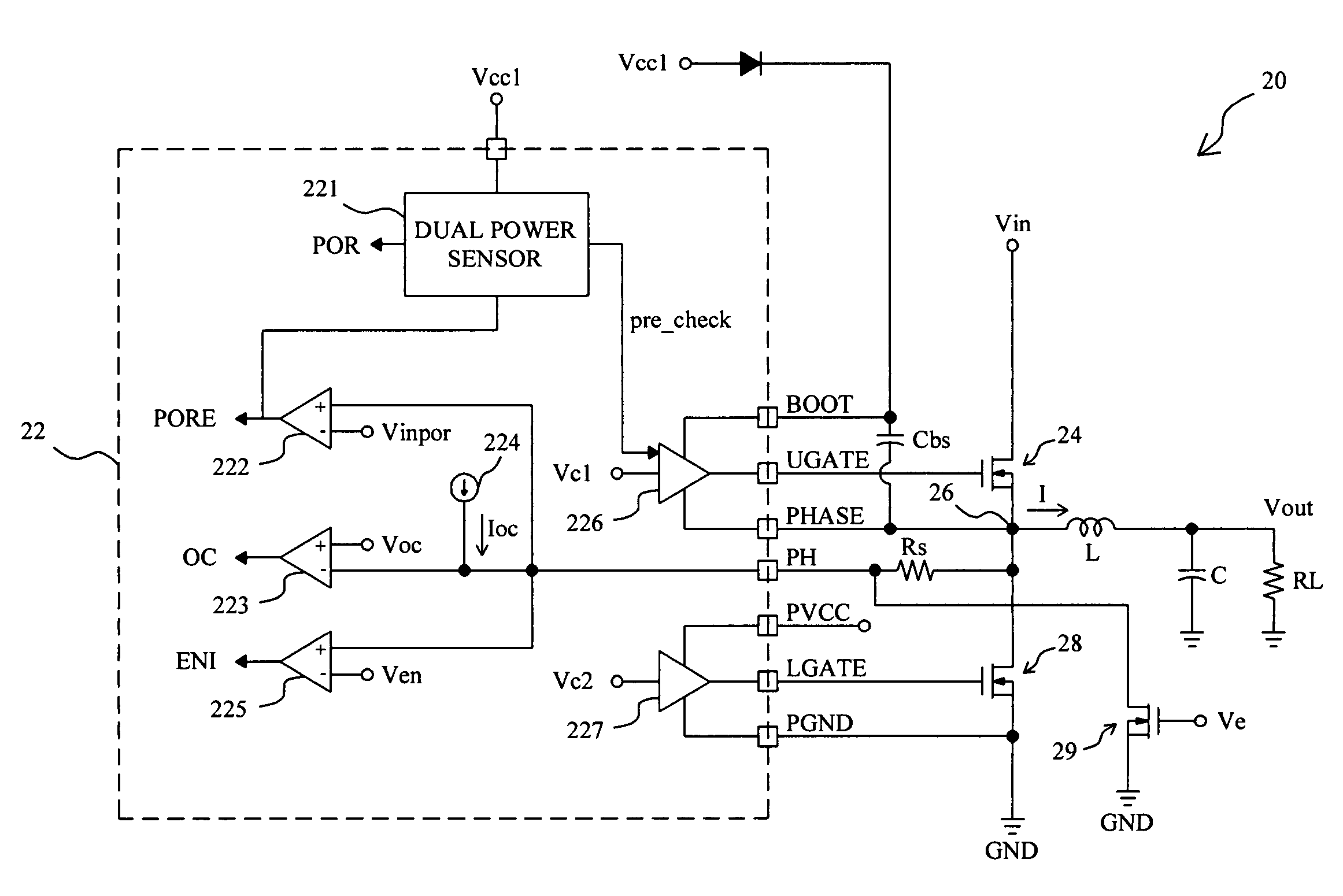
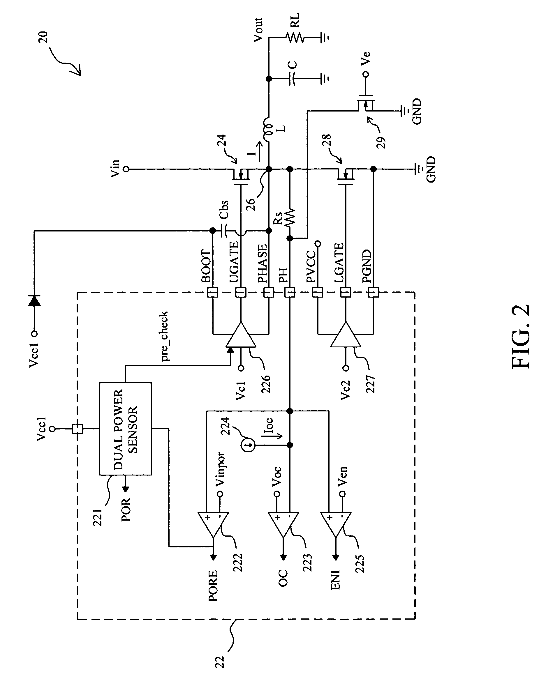
[0013]FIG. 2 shows a circuit diagram of a boost-strap voltage converter 20 according to the present invention, in which a PWM controller chip 22 is used to switch a pair of high side and low side switches 24 and 28 connected in series between a converter power Vin and ground GND to produce an output current I flowing through a phase node 26 between the switches 24 and 28 and an inductor L connected to the phase node 26 to charge a capacitor C to produce an output voltage Vout. The PWM controller chip 22 has a multi-function pin PH connected to the phase node 26 through a sense resistor RS, and a transistor 29 is connected between the multi-function pin PH and ground GND. In the PWM controller chip 22, a dual power sensor 221 and a comparator 222 constitute a power sensing arrangement, a comparator 223 and a current source 224 constitute an over-current protection arrangement, and a comparator 225 in association with the transistor 29 outside the PWM controller chip 22 constitute an ...


PUM


Abstract

For a PWM controller chip in a voltage converter to switch a pair of high side and low side switches connected with a phase node therebetween, a circuit comprises a sense resistor connected between a multi-function pin on the PWM controller chip and the phase node, and an enable arrangement, a power sensing arrangement, and an over-current protection arrangement to detect the voltage on the multi-function pin for accomplishing enable function, power sensing, and over-current protection, respectively.

Description

FIELD OF THE INVENTION[0001]The present invention is related generally to a Pulse Width Modulation (PWM) controller for a voltage converter, and more particularly, to a circuit and method for implementing a multi-function pin on a PWM controller chip in a voltage converter.BACKGROUND OF THE INVENTION[0002]In a voltage converter, PWM controller is used to regulate the output voltage of the voltage converter for supplying for an electronic apparatus. FIG. 1 shows a typical voltage converter 10, in which a high side switch 14 and a low side switch 18 are connected in series between a converter power Vin and ground GND, and a PWM controller chip 12 is connected to the switches 14 and 18 to switch them to produce an output current I flowing through an inductor L connected to a phase node 16 between the switches 14 and 18 to charge a capacitor C to produce an output voltage Vout. When the voltage converter 10 starts up, an enable signal Ve is provided to the PWM controller chip 12 through...

Claims


Application Information

Patent Timeline
Patent Type & Authority Patents(United States)
IPC IPC(8): G05F1/44
CPCH02M1/32H02M3/156
Inventor LIN, PAO-CHUANWANG, CHIN-HUITAI, LIANG-PIN
Owner RICHTEK TECH
Why Eureka
Try Eureka