

Liquid crystal display apparatus
- Summary
- Abstract
- Description
- Claims
- Application Information
AI Technical Summary
Benefits of technology
Problems solved by technology
Method used
Image

Examples
embodiment 1
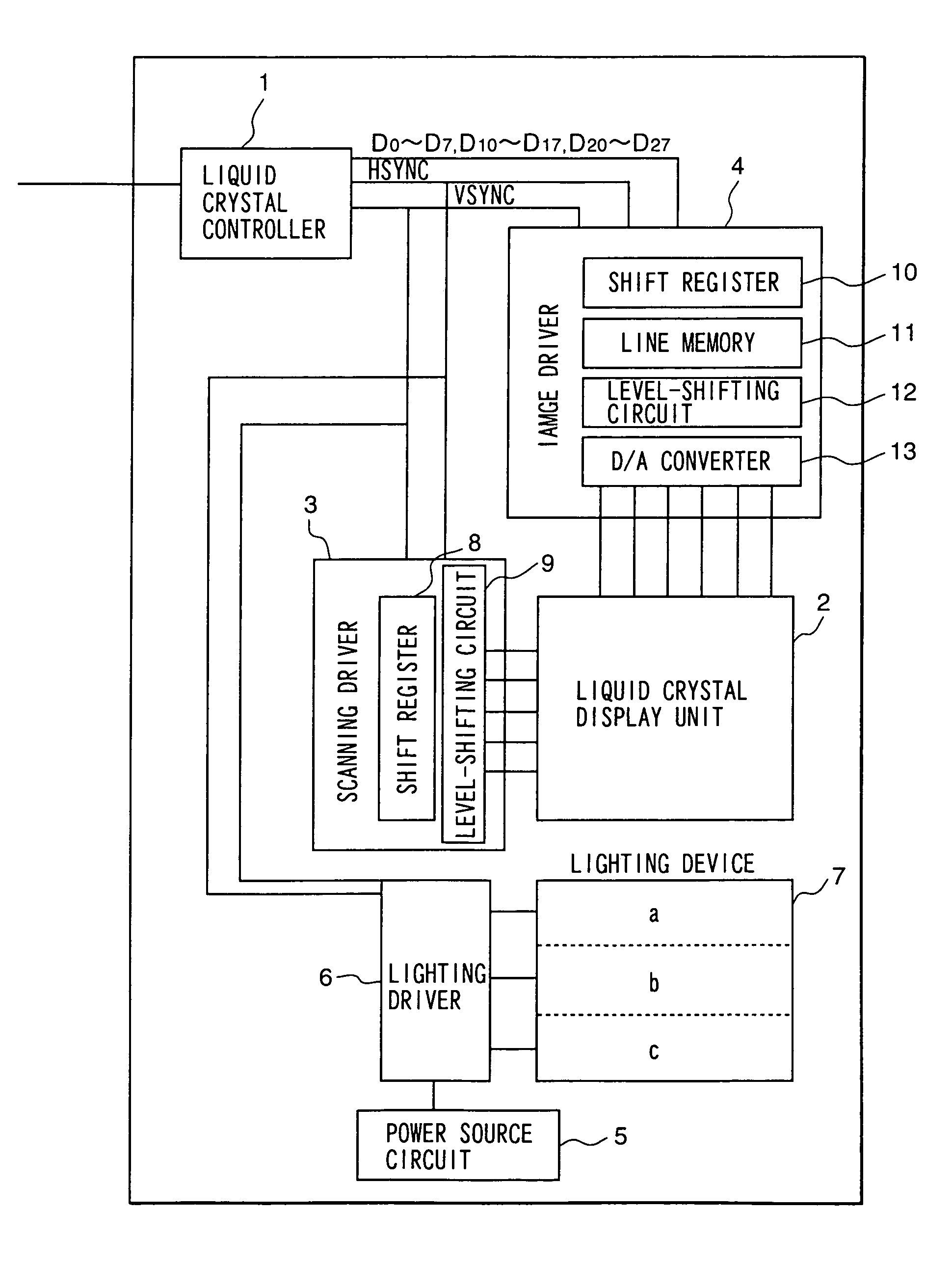
[0023]FIG. 1 shows the composition of a liquid crystal display apparatus of an embodiment according to the present invention. This liquid crystal display apparatus includes a liquid crystal controller 1, a liquid crystal display unit 2, a scanning driver (a scanning electrode-driver circuit) 3, an image driver (a pixel electrode-driver circuit) 4, a power source circuit 5, a lighting driver (a lighting control circuit) 6, and a lighting device 7. The liquid crystal display unit 2 is placed on the lighting device 7. Further, in order to prevent obscurity in the dynamic images, the lighting device 7 is divided into a plurality of regions, and the lighting driver 6 controls the lighting device 7 so that each region lights a corresponding region of the liquid crystal display unit 2. In the following, each unit or part in the liquid crystal display apparatus will be explained.
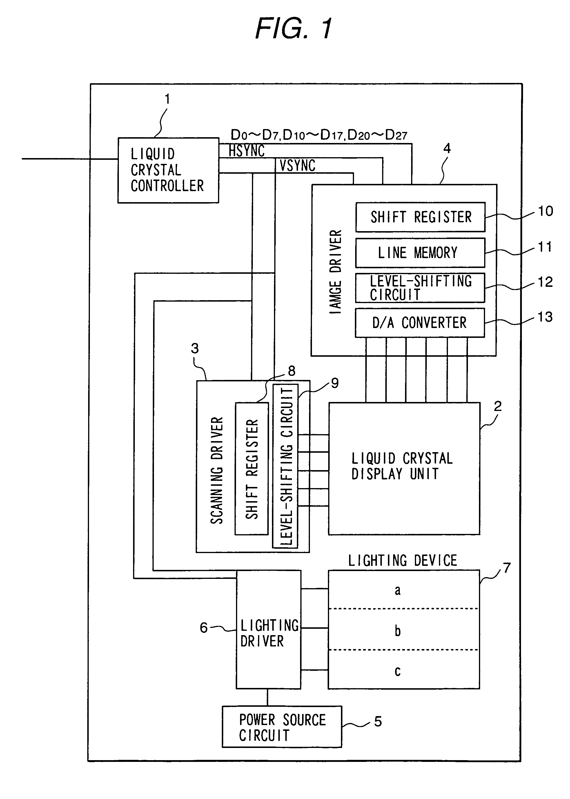
[0024]First, the liquid crystal display unit 2 is explained below. FIG. 2 shows a plan view of a pixel element in...
embodiment 2
[0040]In this embodiment, the device whose composition is shown in FIG. 9 is used as the lighting device 7. The composition of the liquid crystal display apparatus, other than this lighting device, is the same as the composition in Embodiment 1. The feature of the lighting device shown in FIG. 9 is that there are light-reflection plates 80 in each region in the lighting device 7 located such that they almost contact their respective region. In the liquid crystal display apparatus using this lighting device as well as that according to Embodiment 1, even if dynamic images obtained by moving a static image at a visual-angle speed of 10 degrees / s are displayed, there is no perceptible obscurity in the dynamic images. The degradation in the contrast at the boundary between the regions, which is somewhat perceptible in the apparatus according to Embodiment 1, does not occur.
embodiment 3
[0041]In this embodiment, respective shutters located above the lamps 51 are opened and closed without turning the lamps on and off. The output signals from the lighting driver 6 shown in FIG. 1 are input to the shutters. Further, power is fed to each lamp in the lighting device 7 from the power source circuit 5, and the lamps 51 are always turned on.
[0042]FIG. 10 shows the composition of the lighting device 7 in this embodiment. This lighting device 7 includes the light diffusion plate 50, and the plurality of lamps 51 and light-reflection plates 52. Further, the shutters 41, 42, and 43 are located between the light diffusion plate 50 and the lamps 51 for the respective regions a, b, and c. These shutters 41, 42, and 43 are liquid crystal panels made of ferroelectric liquid crystals, and they are connected to the output terminals of the lighting driver 6. When the output signals from the lighting driver 6 are applied to the respective liquid crystal panels 41, 42, and 43, their ope...
PUM
 Abstract
Description
Claims
Application Information