
Optical error simulation system

a technology of optical error simulation and optical communication system, applied in the field of optical error simulation system, can solve the problems of large complex optical network installation or maintenance, large installation or maintenance cost, and high cost, and achieve the effect of accurate simulation, accurate simulation, and high accuracy

Active Publication Date: 2007-06-19
ASTORIA CONSULTANCY LTD
View PDF3 Cites 24 Cited by
  • Summary
  • Abstract
  • Description
  • Claims
  • Application Information

AI Technical Summary

Benefits of technology

[0012]The method of the invention provides a number of advantages over prior art techniques, such as the ability to obtain more accurate estimation of the measure of signal quality (e.g. bit-error rate) over a simulation run of a given duration or, alternatively, an equally accurate estimate over simulation run of substantially reduced duration.

Problems solved by technology

The installation or maintenance of large complex optical networks is often a major and expensive undertaking.
Optical systems operate in the real world and are subject to error rates due to inherent noise in the equipment utilized in the system and in nature generally.
Unfortunately, the methods previously utilized in the simulation of bit error rates often lead to inaccurate simulation results.
This is often a result of utilizing perhaps inappropriate Gaussian noise statistics when simulating bit error rates of an optical system.

Method used


Image

  • Optical error simulation system
  • Optical error simulation system
  • Optical error simulation system

Examples


Embodiment Construction

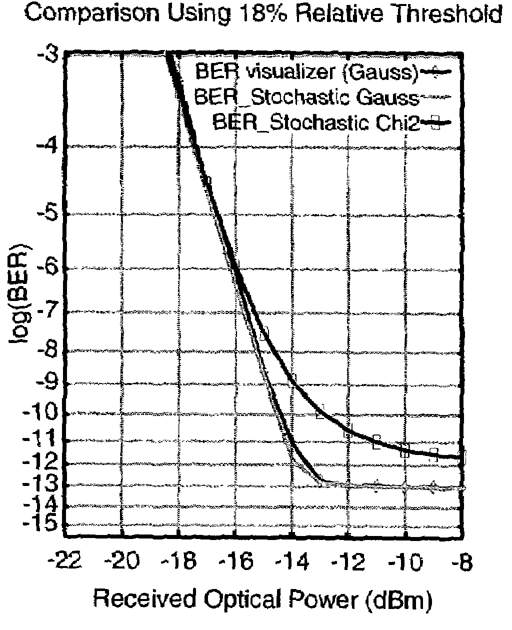
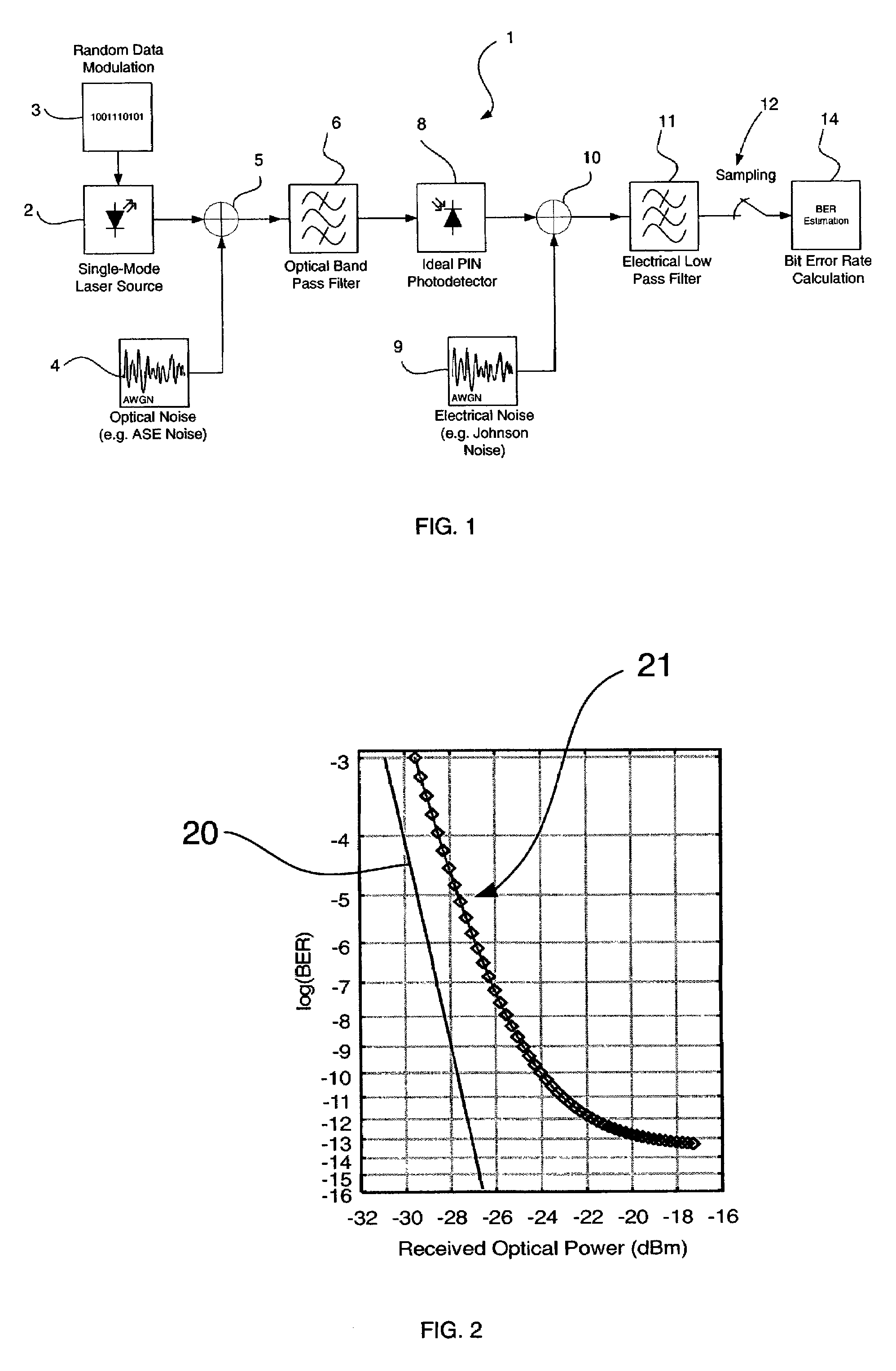
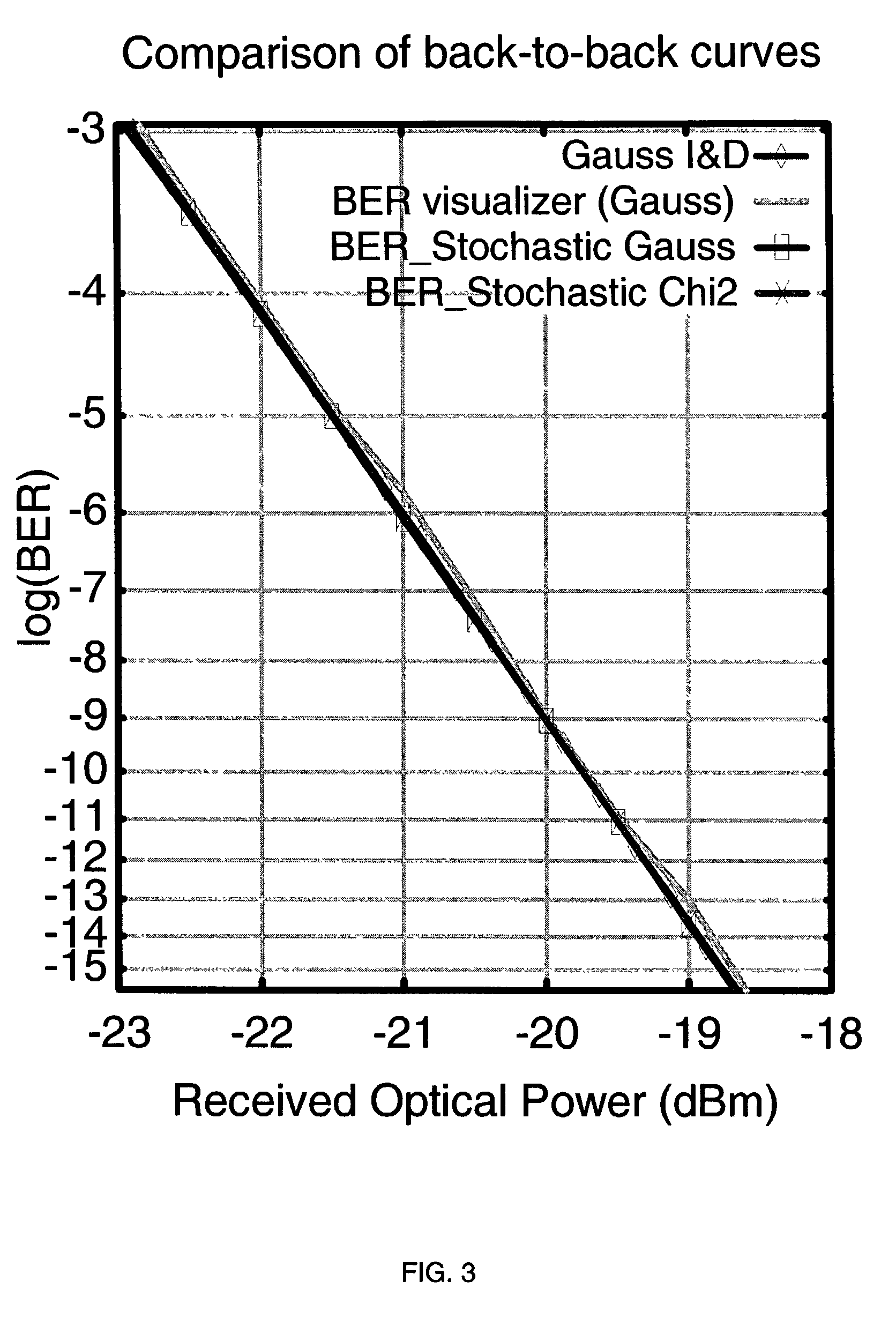
[0030]In the preferred embodiment, there is provided a method for estimating the Bit Error Rate (BER) of a received signal in a computer simulation of an optical transmission system, including the effects of post-detection degradation such as electrical noise and photodetector dark current.

[0031]The preferred method includes the steps of calculating the parameters of non-central χ2 probability density functions that are best-fits to the distributions of the amplitude of the received signal in the absence of post-detection degradation effects and computing the BER of the received signal, including the effects of post-detection degradation effects, using the calculated parameters of the non-central χ2 probability density functions, and the parameters of the post-detection degradation effects.

[0032]By way of explanation of aspects of the method of the preferred embodiment, the operation of the method is described in an example simulation environment. An example system for use with the ...


PUM


Abstract

There is disclosed a method and computer program product for estimating a measure of the quality of the received signal in a computer simulation of an optical transmission system, wherein the simulation includes additive optical noise generated by components within the transmission system. The method and product are able to account for non-Gaussian statistics of noise fluctuations observed in the receivers of optical communications systems, in order to provide for the more accurate simulation of system performance than may be the case using prior art methods based on Gaussian approximation.

Description

CROSS REFERENCE TO RELATED APPLICATIONS[0001]This application claims priority under 35 U.S.C. § 119 to prior Australian Patent Application No. PR8189, filed Oct. 10, 2001, the entire contents of which are incorporated herein by reference.FIELD OF THE INVENTION[0002]The present invention relates to the estimation of signal quality in simulation of optical communications systems.BACKGROUND OF THE INVENTION[0003]Recently, there has been an explosion in the use of optical fibre telecommunications as the main backbone for the carriage of data in telecommunications networks.[0004]The installation or maintenance of large complex optical networks is often a major and expensive undertaking. Obviously, in planning, certain capacity requirements may have to be met. Optical systems operate in the real world and are subject to error rates due to inherent noise in the equipment utilized in the system and in nature generally.[0005]In the planning of large scale optical systems, it is desirable to ...

Claims


Application Information

Patent Timeline
Patent Type & Authority Patents(United States)
IPC IPC(8): G06J1/00G06G7/48H04B10/08H04B10/12G01C11/12G06G7/50H04B10/07
CPCH04B10/07
Inventor SUMMERFIELD, MARK ADAM JOHNKUZMIN, KONSTANTIN
Owner ASTORIA CONSULTANCY LTD
Learn More