
Process for treating waste anesthetic gas

a waste anesthetic and gas technology, applied in the direction of metal/metal-oxide/metal-hydroxide catalysts, ratio control, multiple way valves, etc., can solve the problems of extreme reduction of activity, disordered health, and catalyst activity declin

Inactive Publication Date: 2007-06-26
RESONAC HOLDINGS CORPORATION
View PDF13 Cites 25 Cited by
  • Summary
  • Abstract
  • Description
  • Claims
  • Application Information

AI Technical Summary

Benefits of technology

This approach effectively reduces NOx generation to safe levels, maintains catalyst activity, and allows for compact, cost-effective continuous treatment of waste anesthetic gas, addressing environmental concerns by rendering harmful gases harmless.

Problems solved by technology

It is known that as a result of long term inhalation of the anesthetic gas leaked in the operating room, the health is disordered.
In addition, when moisture in an amount of, for example, approximately from 1 to 3% is present in the reaction gas, the catalyst may decrease in the activity, and this remains as a problem to be solved.
When a waste anesthetic gas is fed as it is to a nitrous oxide decomposition catalyst, decrease in the specific surface area of the nitrous oxide decomposition catalyst is incurred in some cases to cause extreme reduction of the activity.
The above method (2) of cooling and thereby removing volatile anesthetic contained in the waste anesthetic gas proposed by Arai et al has a problem in the profitability because a volatile anesthetic gas removing device and a cooling unit for cooling the removing device must be installed in each operating room.
Furthermore, in the case of treating a large amount gas flown from the pipeline to which the waste anesthetic gases discharged from respective operating rooms are converged, there arises a problem that the volatile anesthetic cannot be satisfactorily removed.

Method used

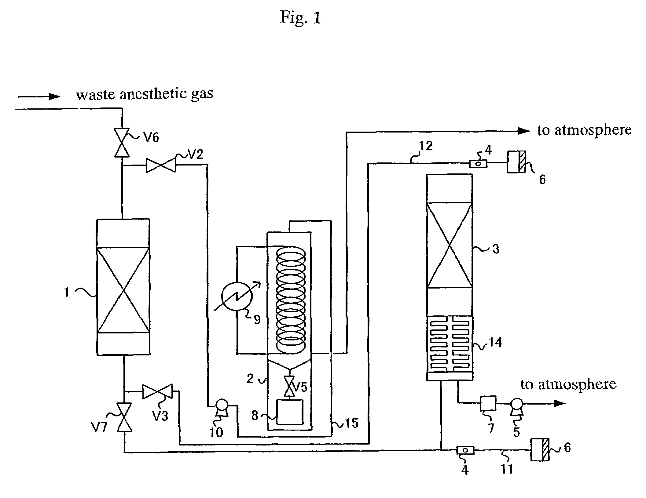
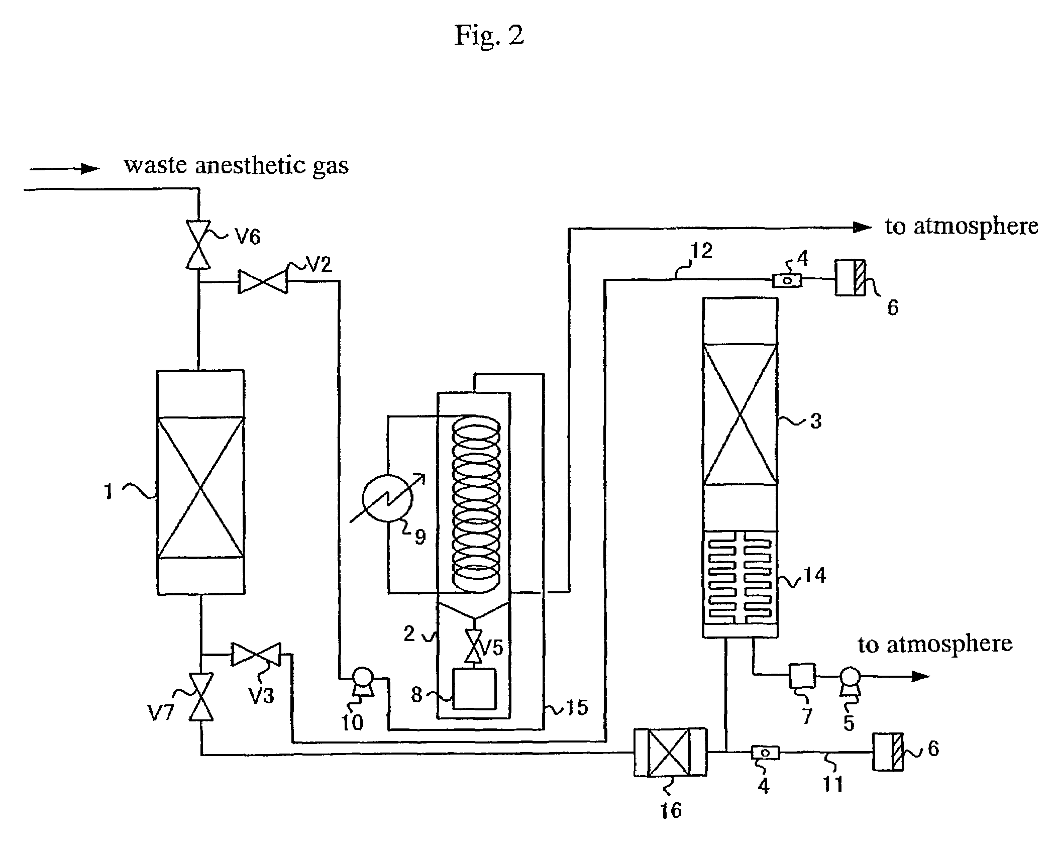
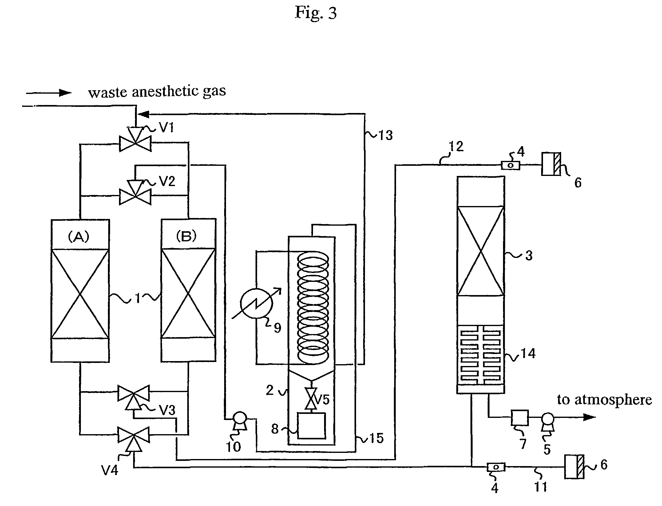

Image

  • Process for treating waste anesthetic gas
  • Process for treating waste anesthetic gas
  • Process for treating waste anesthetic gas

Examples


Embodiment Construction

[0065]The present invention is described in detail below.

[0066]The process for treating a waste anesthetic gas containing a volatile anesthetic and nitrous oxide of the present invention is described below.

[0067]The process for treating a waste anesthetic gas of the present invention is characterized in steps of contacting a waste anesthetic gas containing a volatile anesthetic and nitrous oxide with an adsorbent and contacting the gas with a catalyst for decomposing the nitrous oxide.

[0068]The process for treating a waste anesthetic gas of the present invention is characterized in that a step (1) of introducing a waste anesthetic gas containing a volatile anesthetic and nitrous oxide into an adsorbing cylinder and contacting the gas with an adsorbent filled in said adsorbing cylinder, thereby adsorption-removing the volatile anesthetic contained in the waste anesthetic gas is first performed, and then, a step (2) of introducing the gas containing nitrous oxide discharged from the s...


PUM

PropertyMeasurementUnit
temperatureaaaaaaaaaa

Abstract

To provide a process and an apparatus for treating a waste anesthetic gas containing a volatile anesthetic and nitrous oxide discharged from an operating room by introducing the gas into an adsorbing cylinder filled with an adsorbent, where the volatile anesthetic contained in the waste anesthetic gas is adsorbed and thereby removed, and successively introducing the gas into a catalyst layer filled with a nitrous oxide decomposition catalyst, where nitrous oxide is decomposed into nitrogen and oxygen. By using the process and the apparatus for treating a waste anesthetic gas of the present invention, a volatile anesthetic having a possibility of destroying the ozone layer or nitrous oxide as a global warming gas can be made harmless while preventing the release into atmosphere.

Description

CROSS REFERENCE TO RELATED APPLICATIONS[0001]This application is an application filed under 35 U.S.C. §111(a) claiming benefit pursuant to 35 U.S.C. §119(e)(1) of the filing dates of U.S. Provisional Application No. 60 / 241,743 filed Oct. 20, 2000 pursuant to 35 U.S.C. §111(b).TECHNICAL FIELD TO WHICH THE INVENTION BELONGS[0002]The present invention relates to a process and an apparatus for treating a waste anesthetic gas containing a volatile anesthetic and nitrous oxide discharged from an operating room.BACKGROUND ART[0003]Since 1960, contamination of an operating room by anesthetic gas and adverse effect of the anesthetic gas on the health of workers in the operating room have been taken as a matter of issue. It is known that as a result of long term inhalation of the anesthetic gas leaked in the operating room, the health is disordered. The anesthetic gas means a mixed gas containing nitrous oxide, a volatile anesthetic and oxygen, and the waste anesthetic gas means anesthetic ga...

Claims


Application Information

Patent Timeline
Patent Type & Authority Patents(United States)
IPC IPC(8): A61M16/00B01D46/00B01J8/00C01B21/00A61M16/01B01D53/04B01D53/34B01D53/70B01D53/86B01D53/94B01J20/08B01J20/10B01J20/18B01J20/20B01J20/28B01J20/34B01J23/58
CPCA61M16/009B01D53/04B01D53/8625B01D53/8631A61M16/0093B01D53/86B01D2257/2064B01D2257/2066B01D2257/402B01D2259/40B01D2259/40001B01D2259/40086B01D2259/4533Y02C20/10A61M2230/437B01D53/75
Inventor HOTTA, MASATOSHIOKA, MASAKAZUFURUSE, YOSHIOATOBE, HITOSHICHAEN, SHIGEHIRO
Owner RESONAC HOLDINGS CORPORATION
Learn More