Thermoelectric devices utilizing double-sided Peltier junctions and methods of making the devices

a technology of double-sided peltier junction and thermoelectric device, which is applied in the manufacture/treatment of thermoelectric device, generator/motor, lighting and heating apparatus, etc., can solve problems such as complicated manufacturing process, and achieve the effect of simplifying the manufacturing process of thermoelectric devi

Active Publication Date: 2007-06-26
LAIRD THERMAL SYST INC
View PDF48 Cites 51 Cited by
  • Summary
  • Abstract
  • Description
  • Claims
  • Application Information

AI Technical Summary

Benefits of technology

[0009]Another object of the present invention is to simplify the manufacture of thermoelectric device.

Problems solved by technology

The n and p elements are intermingled on the same side of header 17 during module fabrication, which can complicate the manufacturing process.

Method used


Image

  • Thermoelectric devices utilizing double-sided Peltier junctions and methods of making the devices
  • Thermoelectric devices utilizing double-sided Peltier junctions and methods of making the devices
  • Thermoelectric devices utilizing double-sided Peltier junctions and methods of making the devices

Examples


Embodiment Construction

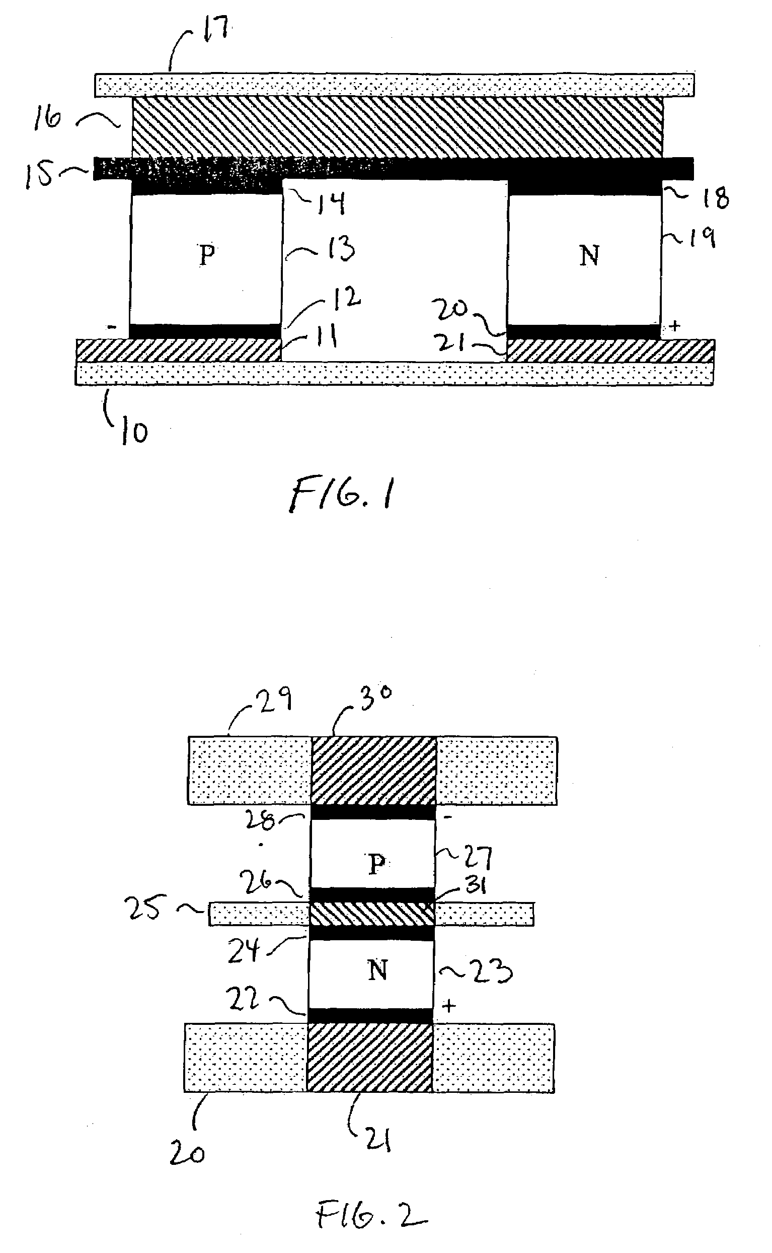
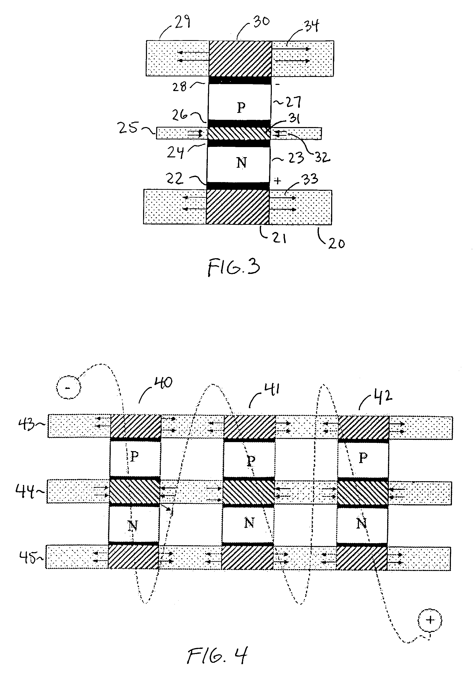
[0037]Referring now to the drawings, wherein like reference numerals designate identical, or corresponding parts throughout the several views, and more particularly to FIG. 2 thereof, FIG. 2 is a first embodiment of the device according to the present invention. FIG. 2 illustrates a schematic diagram of The device where the voltage polarities (+,−) are shown for cooling. It is noted that the drawing is not to scale, but is drawn to illustrate the features of the device. Dimensions of the elements are discussed below, but the present invention is not limited to those specific dimensiona. The device includes a plurality of thermoelements disposed on opposite sides of a cooling header. A p thermoelement 27 is connected on one side by Peltier junction metalization 28 to an electrical lead 30 on a first heat sink 29. The Peltier junction metalization is electrically conductive. On the other side, p thermoelement 27 is connected to a contact 31 on heat source (header) 25 by Peltier juncti...


PUM


Abstract

A thermoelectric device and method of manufacturing the device, where thermoelectric elements of opposite conductivity type are located on respective opposing sides of a heat source member. Heat sinks are disposed on opposite sides of the thermoelectric elements. Peltier metal contacts are positioned between the thermoelectric elements and each of the heat source member and heat sinks. A plurality of devices may be arranged together in a thermally parallel, electrically series arrangement, or in a thermally parallel, electrically parallel arrangement. The arrangement of the elements allow the direction of current flow through the pairs of elements to be substantially the same as the direction of current flow through the metal contacts.

Description

CROSS-REFERENCE TO RELATED DOCUMENTS[0001]This application is related to and claims priority under 35 U.S.C. §119(e) to U.S. Provisional Application No. 60 / 372,139 filed in the United States Patent and Trademark Office on Apr. 15, 2002, the entire contents of which is incorporated herein by reference. This application is related to U.S. Pat. No. 6,300,150 issued Oct. 9, 2001, the entire contents of which is incorporated herein by reference. This application is related to U.S. Pat. No. 6,071,351 issued Jun. 6, 2002, the entire contents of which is incorporated herein by reference. This application is related to U.S. Pat. No. 6,505,468 issued Jan. 14, 2003, the entire contents of which is incorporated herein by reference. This application is also related to U.S. Provisional Application No. 60 / 253,743, “Spontaneous Emission Enhanced Heat Transport Method and Structures for Cooling, Sensing, and Power Generation”, filed Nov. 29, 2000, the entire contents of which is incorporated herein ...

Claims


Application Information

Patent Timeline
Patent Type & Authority Patents(United States)
IPC IPC(8): H01L35/04H01L35/08H01L35/14H01L35/16H01L35/30H01L35/32H01L35/34H02N11/00
CPCB82Y10/00H01L35/08H01L35/16H01L35/30H01L35/32H10N10/817H10N10/852H10N10/13H10N10/17H10N10/80
Inventor VENKATASUBRAMANIAN, RAMASIIVOLA, EDWARD P.
Owner LAIRD THERMAL SYST INC
Why Eureka
Try Eureka