
Solar sensor including reflective element to transform the angular response

a solar sensor and reflective element technology, applied in the field of solar sensors, can solve the problems of significant reduction of overall signal current, drawback of cosine response in some solar sensors,

Inactive Publication Date: 2007-06-26
CONTROL DEVICES
View PDF154 Cites 13 Cited by
  • Summary
  • Abstract
  • Description
  • Claims
  • Application Information

AI Technical Summary

Benefits of technology

"The present invention provides a method to adjust the response characteristics of a solar sensor by combining both solar radiation blocking and reflecting features. This allows for accurate detection of solar radiation regardless of its angular position. The invention also includes an apparatus with a reflective surface that is curved, which can be spherical, parabolic, or conical. The apparatus can be used to detect the angular position of a radiation source. The technical effects of the invention include improved accuracy and reliability of solar sensor readings, regardless of the position of the sun or other radiation source."

Problems solved by technology

This cosine response is a drawback in some types of solar sensors.
One difficulty with this approach is the significant reduction in overall signal current due to the loss of light through the diffuser material.

Method used


Image

  • Solar sensor including reflective element to transform the angular response
  • Solar sensor including reflective element to transform the angular response
  • Solar sensor including reflective element to transform the angular response

Examples


Embodiment Construction

[0020]While the present invention may be embodied in many different forms for the purpose of promoting an understanding of the principles of the invention, reference will now be made to the embodiments illustrated in the drawings and specific language will be used to describe the same. It will nevertheless be understood that no limitation of the scope of the invention is thereby intended. Any alterations and further modifications in the described embodiments, and any further applications of the principles of the invention as described herein are contemplated as would normally occur to one skilled in the art to which the invention relates.

[0021]This application incorporates by reference the following U.S. patent applications: Ser. No. 220,021, filed Jul. 15, 1988, which issued as U.S. Pat. No. 4,933,550; Ser. No. 08 / 653,818, filed May 28, 1996, which issued as U.S. Pat. No. 5,670,774; Ser. No. 09 / 188,824, filed Nov. 9, 1998, which issued as U.S. Pat. No. 6,084,228; Ser. No. 09 / 554,29...


PUM


Abstract

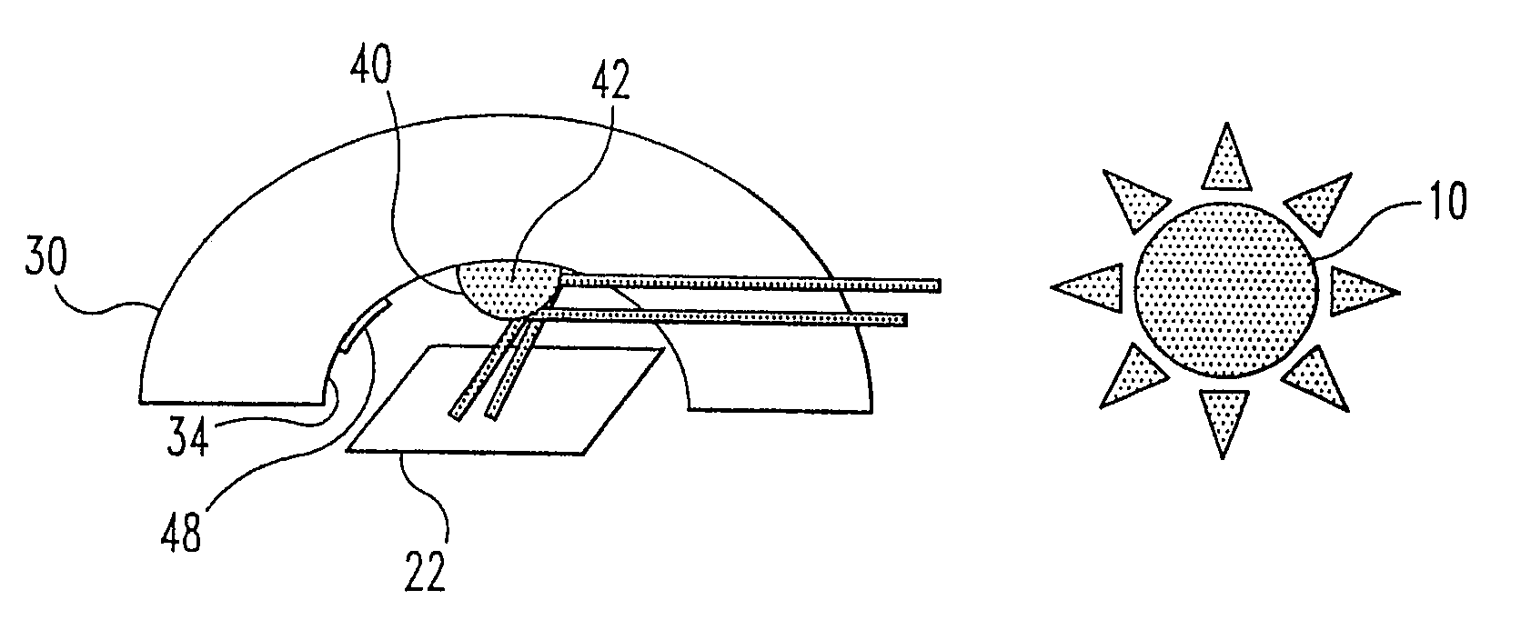
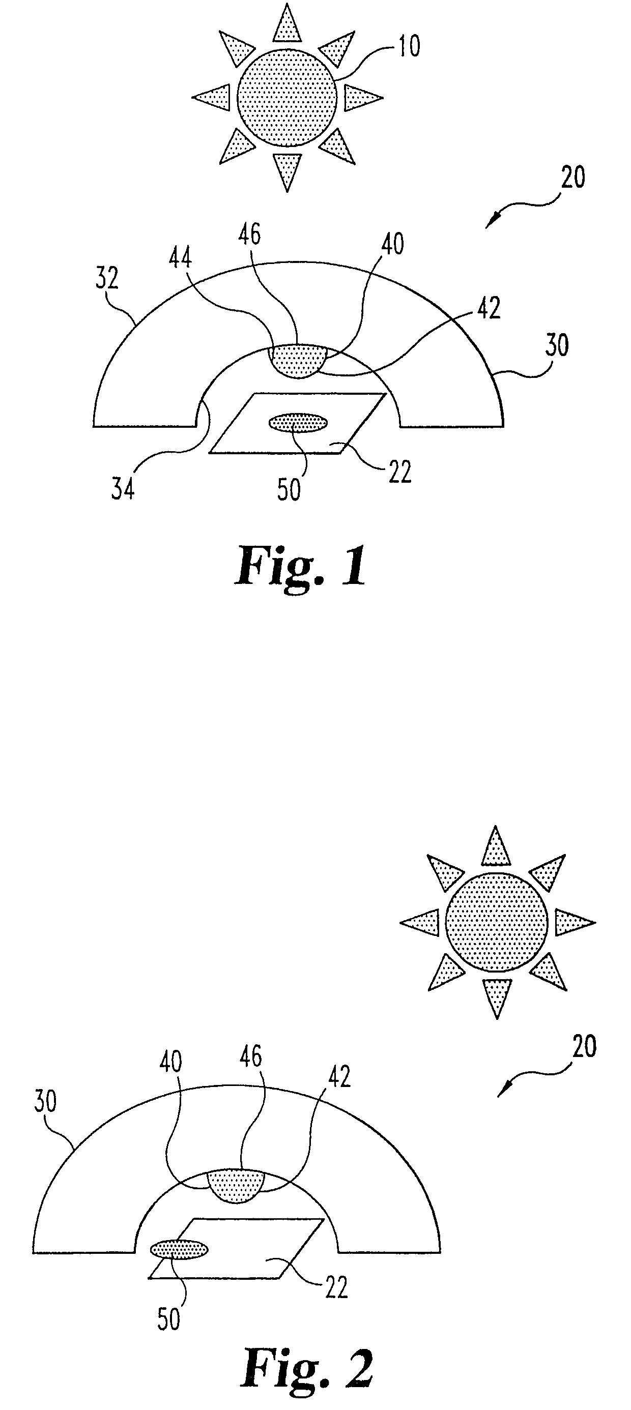
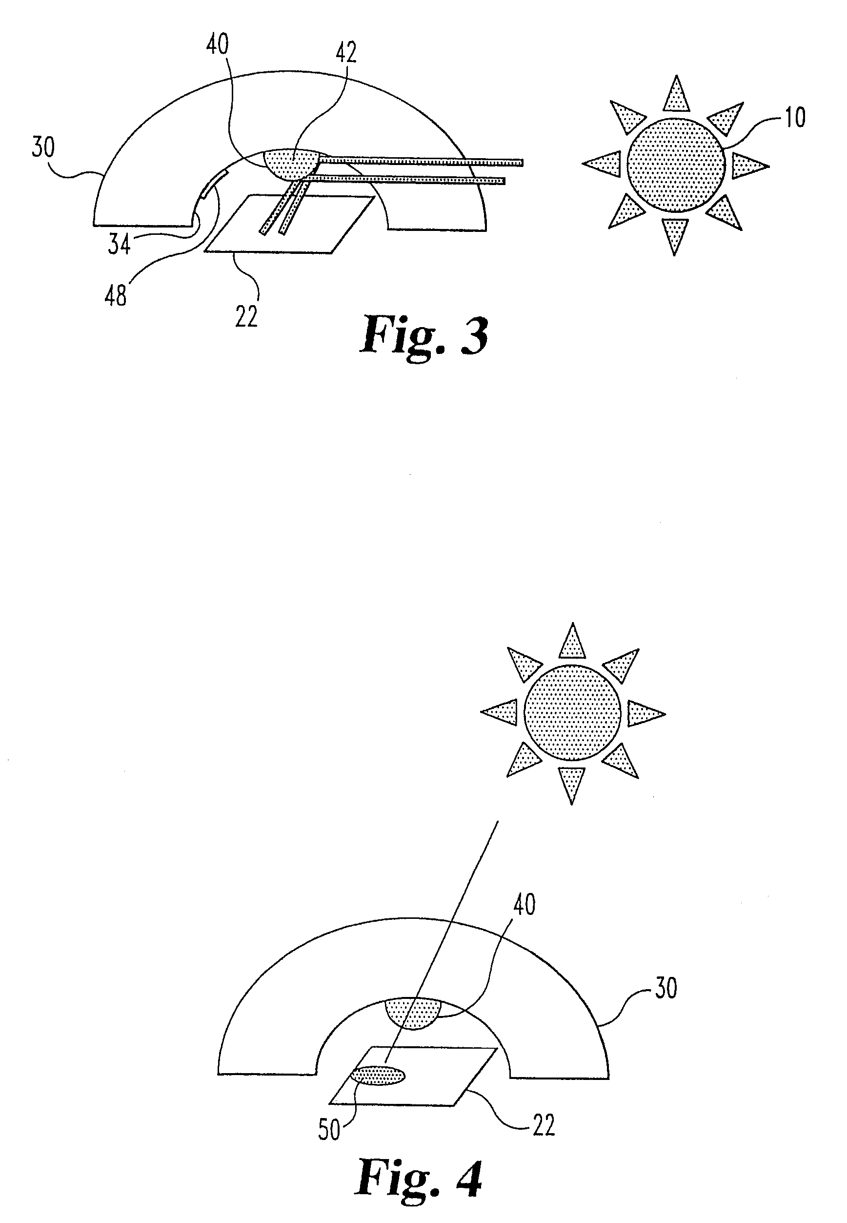
A solar sensor that utilizes a blocking element and curved reflective element between the sun and a photo-sensitive electronic device to provide high signal levels and the ability to shape the angular response of the overall sensor. A particular angular response can be achieved by combining the attenuating affects of the blocking element with the increased response affects of the curved reflector. These two elements may be combined into one physical structure, or may be separate. Further, the present invention contemplates the use of multiple blocking elements and multiple reflectors.

Description

[0001]The present application is a divisional of application Ser. No. 10 / 738,726, filed Dec. 17, 2003, which claims the benefit of U.S. Provisional Application No. 60 / 466,815, filed Apr. 30, 2003, each of which are hereby incorporated by reference their entirety.FIELD OF THE INVENTION[0002]The present invention relates to solar sensors for that respond to the position of the sun, and in particular solar sensors used for adjustment of climate controls of a vehicle.BACKGROUND OF THE INVENTION[0003]Generally, photodiodes have a cosine angular response, meaning that the peak response of the photodiode is achieved at a normal angle of incidence where light is impinging perpendicular to the surface. This response gradually decreases according to the cosine function to a zero output at 90°.[0004]This cosine response is a drawback in some types of solar sensors. In some vehicles, a solar sensor is used to measure solar heating by sunlight. The sensor represents a sampling of the heating aff...

Claims


Application Information

Patent Timeline
Patent Type & Authority Patents(United States)
IPC IPC(8): G01C21/02G01C1/00F24S50/20G01J1/04G01J1/42
CPCG01J1/04G01J1/0414G01J1/0437G01J1/42G01J2001/0485
Inventor CLUGSTON, JR., P EDWARD
Owner CONTROL DEVICES
Learn More