Computational geometry using control geometry having at least two dimensions

a control geometry and computation technology, applied in computing, instruments, data processing applications, etc., can solve the problems of inability to easily and efficiently interpolate from other subportions, no cad system wherein a designer (or more generally, a user) of geometric objects can easily and efficiently, and designers/users may encounter long delays. , to achieve the effect of efficient regenerating

Inactive Publication Date: 2007-06-26
CAD-SENSE LLC
View PDF41 Cites 35 Cited by
  • Summary
  • Abstract
  • Description
  • Claims
  • Application Information

AI Technical Summary

Benefits of technology

[0035]The present invention is a computational geometric design system that is capable of sufficiently efficient computations so as to allow real-time deformations to objects such as surfaces while a user is supplying the object modifying input. Thus, the present invention is a paradigm shift away from typical CAD systems since, in a typical CAD system the user must supply input for changing or modifying a geometric object and subsequently explicitly request processing of the input to commence. Thus, in such prior art CAD systems, the user receives feedback about his / her design at discrete user requested times. Instead, with the present invention, updates may be processed in real-time immediately upon input receipt without the user explicitly indicating that update processing is to be performed.
[0036]Given the enhanced computational efficiency of the present invention, a user of the present invention can more efficiently perform iterative approximations to a geometric object being designed. The user may speedily design without the need to precisely calculate design geometric characteristics for portions of the object where such precision may not be necessary. That is, the user can be less concerned about getting it “right the first time” since the ease of modification and speed of computing modifications allows the user to more rapidly approximate and / or prototype a geometric object. Thus, the present invention can have substantial efficiency benefits in that for many geometrically designed objects (including machined parts), substantial portions of such objects may be satisfactorily designed with a wide range of geometric characteristics.
[0045]It is also within the scope of the present invention that the geometric objects Si used to generate a blended geometric object S may be such that the Si's can be modified indirectly via other geometric objects from which the Si's may be themselves generated. For example, if S is a surface blended from isocline ribbons S1 and S2 (having corresponding profiles P1 and P2, respectively), and the ribbon S1 is interpolated from the profile handle, the isocline handle, and the ribbon tangent at the end points of P1, then the present invention provides user interaction techniques for modifying such handles and / or ribbon tangents for thereby modifying the blended surface S. Moreover, in one user interface technique, only the handles may be displayed, wherein such handles are displayed as connected to the blended surface S. Thus, by changing such handles, the blended surface changes. Note that such user interaction techniques may be responsive in real time to user changes to such handles and / or ribbon tangents. Thus, a user's design intent may be immediately displayed while the user is inputting such changes. Accordingly, using the present invention, user interactions in the design process may become closer to the techniques in used in constructing actual geometric models rather than prior art CAD user interaction techniques.
[0046]It is another aspect of the present invention that various geometric constraint criteria are capable of being applied to geometric objects generated according to the present invention. In particular, features and / or subgeometry of a geometric object O0 are capable of being constrained to lie within another geometric object, O1, so that as O1 is deformed, the features and / or subgeometry of O0 deform correspondingly, and thereby cause O0 to deform accordingly. For example, the present invention allows an object space point p to be defined (i.e., parameterized) so that it must remain in / on a given geometric object O1, where O1 may be a curve, surface, volume or solid. Thus, as O1 is deformed, O0 also deforms. Moreover, instead of a point p, other geometric subobjects may also be similarly constrained, such as curves, surfaces or solids. Additionally, features of a geometric object O0 such as control points, handles (of various types, e.g., profile and isocline), normals, twist vectors, etc. may also be similarly constrained by the present invention so that as O1 is deformed, O0 is caused to also deform. For instance, using the geometric object interpolation techniques provided by the present invention, e.g., Formula (I) and variations thereof, the geometric object O0 can be efficiently regenerated (e.g., reinterpolated) substantially in real-time when constrained features and / or subgeometries of O0 are correspondingly deformed with a deformation of O1. More particularly, this aspect of the present invention provides for the combining of various geometric objects hierarchically so that geometric deformation control of a parent object causes corresponding geometric changes in dependent child geometric objects. For example, when a surface patch represents fine scale detail of a larger surface, it may be advantageous to attach the fine detail surface patch to the larger surface to thereby give a user automatic control over the shape of the fine detail surface patch by controlling the shape of the larger surface. Moreover, similar hierarchical control can be provided with other geometric objects of types such as curves, points and three-dimensional deformation spaces.

Problems solved by technology

Thus, the designer typically constructs such feature curves and positions them where the intended surface is likely to change its geometric shape in a way that cannot be easily interpolated from other subportions of the surface already designed.
There has heretofore, however, been no CAD system wherein a designer (or more generally, user) of geometric objects can easily and efficiently express his / her design intent by inputting constraints and having the resulting geometric object be fair.
That is, the designer / user may encounter lengthy delays due to substantial computational overhead and / or the designer / user may be confronted with non-intuitive geometric object definition and deformation techniques that require substantial experience to effectively use.
For example, many prior art CAD systems provide techniques for allowing surfaces to be designed and / or deformed by defining and / or manipulating designated points denoted as “control points.” However, such techniques can be computationally expensive, non-intuitive, and incapable of easily deforming more than a local area of the surface associated with such a control point.
However, a designer's intent may not easily correspond to a surface design technique using such control vectors since each of the control vectors typically corresponds to only a single point of the surface isolated from other surface points having corresponding control vectors.
Thus, such techniques are, at most, only able to deform an area of the surface local to such points having corresponding control vectors.
Additionally, such prior art CAD systems may also have difficulties in precisely performing blending and trimming operations.
For example, two geometric objects intended to abut one another along a common boundary may not be within a sufficient tolerance to one another at the boundary.
That is, there may be sufficiently large gaps between the geometric objects that the boundary may not be considered “water tight,” which may be problematic in certain machining operations and other operations like Boolean operations on solids.
This type of evaluation is usually fast and efficient, but does not give function values at chosen positions between the increments.

Method used


Image

  • Computational geometry using control geometry having at least two dimensions
  • Computational geometry using control geometry having at least two dimensions
  • Computational geometry using control geometry having at least two dimensions

Examples


Embodiment Construction

1. Introduction

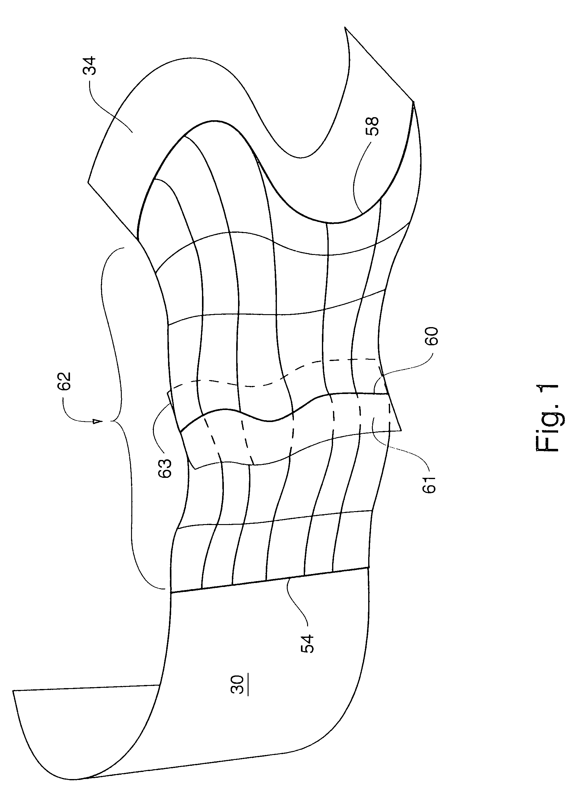
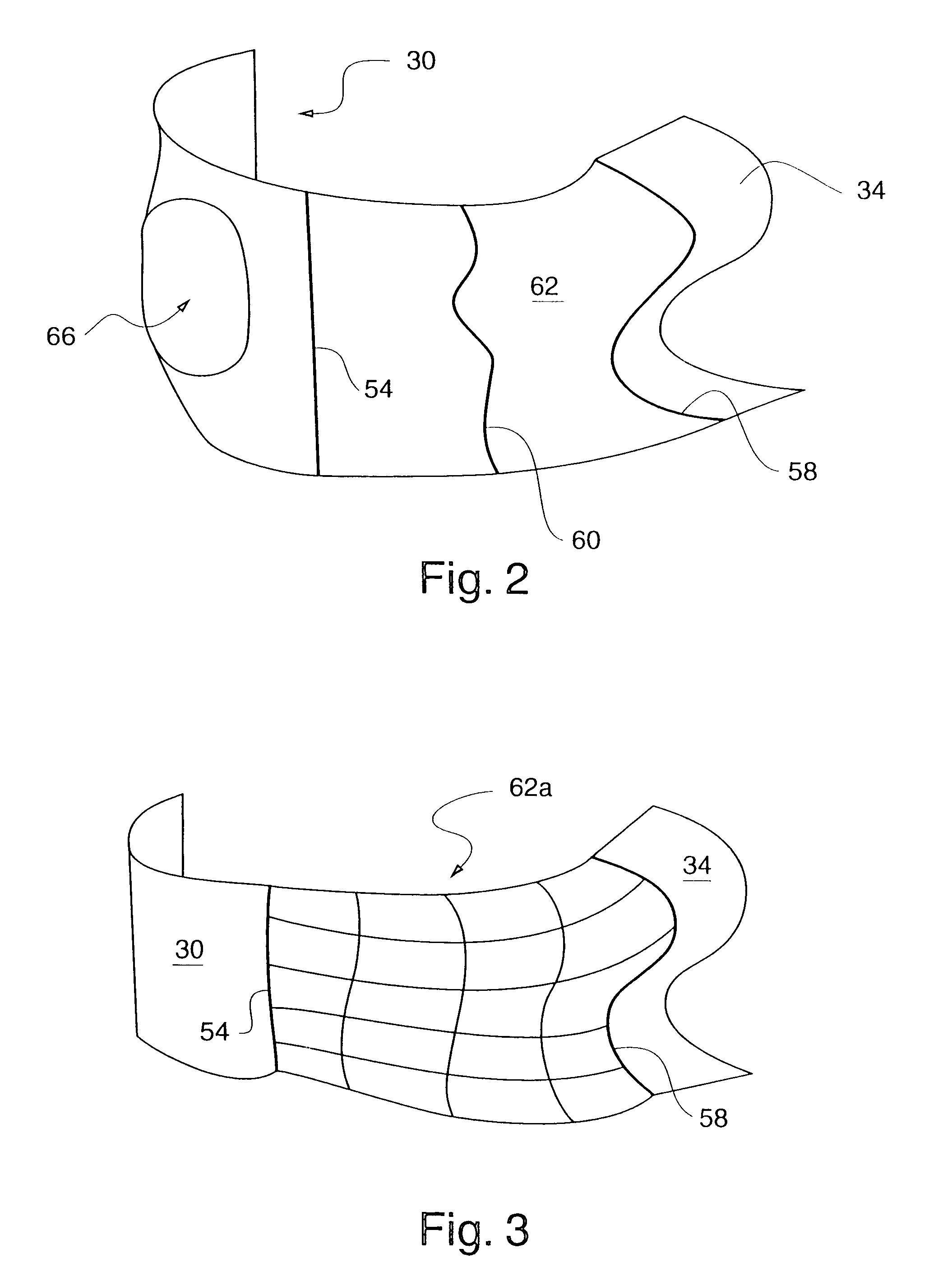
[0091]FIG. 1 illustrates the use of an embodiment of the present invention for designing a surface 62 that interpolates any two parametric surfaces such as between the half cylinder surface 30 and the surface 34. That is, the surface 62 is generated via a novel surface interpolation process, wherein constraints on surface 62 shape are provided by the feature curves 54, 58 and 60, and their associated novel control geometry (e.g., isocline ribbons). In particular, the following constraints are satisfied by the surface 62:[0092](a) one or more geometric characteristics of the surface 30 along the feature curve 54 are imposed on the surface 62,[0093](b) one or more geometric characteristics of the surface 34 along the feature curve 58 are imposed on the surface 62, and[0094](c) the surface 62 interpolates through the feature curve 60, wherein the surface 62 tangents along the extent of curve 60 are derived from (e.g., identical to) the isocline ribbons 61 and 63.

Thus, us...


PUM


Abstract

A method and system for computer aided design (CAD) is disclosed for designing geometric objects. The present invention interpolates and / or blends between such geometric objects sufficiently fast so that real time deformation of such objects occurs while deformation data is being input. Thus, a user designing with the present invention obtains immediate feedback to input modifications without separately entering a command for performing such deformations. The present invention utilizes novel computational techniques for blending between geometric objects, wherein weighted sums of points on the geometric objects are used in deriving a new blended geometric object. The present invention is particularly useful for designing the shape of surfaces. Thus, the present invention is applicable to various design domains such as the design of, e.g., bottles, vehicles, and watercraft. Additionally, the present invention provides for efficient animation via repeatedly modifying surfaces of an animated object such as a representation of a face.

Description

CROSS-REFERENCE TO RELATED APPLICATIONS[0001]The present application is a divisional of U.S. patent application Ser. No. 09 / 360,029 filed Jul. 23,1999, which claims priority from U.S. Provisional Application Ser. No. 60 / 093,892, filed Jul. 23, 1998, and from U.S. Provisional Application Ser. No. 60 / 116,199, filed Jan. 15, 1999, all of which are incorporated herein by reference in their entirety.FIELD OF THE INVENTION[0002]The present invention relates to a system and method for performing computer aided design, and, in particular, to efficient computational techniques for blending between representations of geometric objects.BACKGROUND[0003]A designer using a computer aided design (CAD) computational system will typically approach the design of a free form geometric object (such as a surface) by first specifying prominent and / or necessary subportions of the geometric object through which the object is constrained to pass. Subsequently, a process is activated for generating the geome...

Claims


Application Information

Patent Timeline
Patent Type & Authority Patents(United States)
IPC IPC(8): G06T15/00G06T17/30
CPCG06T17/30Y10S715/964
Inventor LEE, JOHN N.ROCKWOOD, ALYNHAGEN, LANCEHAGEN, SCOTT
Owner CAD-SENSE LLC
Why Eureka
Try Eureka