Drive power supply and fail determination method

a technology of failure determination and drive power supply, which is applied in the direction of electric generator control, dynamo-electric converter control, dynamo-electric gear control, etc., can solve the problem of not being able to reliably determine whether an abnormality has occurred in the drive power supply independent of the voltage of the terminal, and achieve the effect of lowering costs

Active Publication Date: 2007-06-26
AISIN AW CO LTD
View PDF8 Cites 11 Cited by
  • Summary
  • Abstract
  • Description
  • Claims
  • Application Information

AI Technical Summary

Benefits of technology

[0012]It is an object of the present invention to solve the problems of the aforementioned conventional drive power supply apparatus, and provide a drive power supply and fail determination method that allows for lowered costs and a definite determination of abnormalities generated in the drive power supply.
[0014]In this case, for example, the feedback voltage and the drive voltage are changed when an abnormality is occurs on a predetermined terminal and the voltage fluctuates, similar to when an IG short occurs, therefore, it is impossible to reliably determine whether an abnormality has occurred in the drive power supply independent of the voltage of the terminal. Also, since it is not necessary to separately provide an IG short detecting circuit, not only can the drive power supply apparatus be simplified, but the cost of the drive power supply apparatus can be reduced as well.

Problems solved by technology

In this case, for example, the feedback voltage and the drive voltage are changed when an abnormality is occurs on a predetermined terminal and the voltage fluctuates, similar to when an IG short occurs, therefore, it is impossible to reliably determine whether an abnormality has occurred in the drive power supply independent of the voltage of the terminal.

Method used


Image

  • Drive power supply and fail determination method
  • Drive power supply and fail determination method
  • Drive power supply and fail determination method

Examples


Embodiment Construction

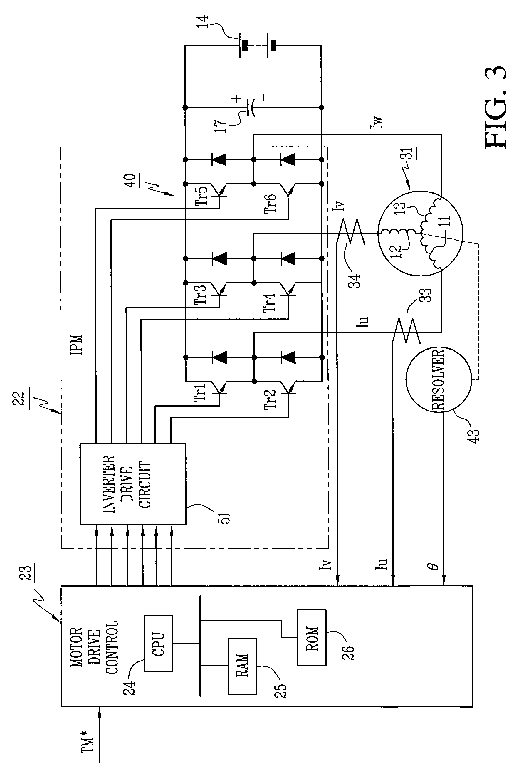
[0027]One embodiment of the present invention is described in detail with reference to the accompanying FIGS. 1–5. In FIG. 3 which is a control circuit diagram of an electric vehicle drive control device according to an embodiment of the present invention, reference numeral 22 denotes an IPM and reference numeral 23 denotes a motor drive control that includes a computer controlled by various programs, data and the like. Reference numeral 31 denotes an electric drive motor such as an AC brushless drive motor. The IPM 22 is provided with an inverter 40 and an inverter drive circuit 51. The drive motor 31 is equipped with a rotor (not shown) and a stator (represented by coils 11, 12 and 13) surrounding the rotor.

[0028]The rotor is equipped with a rotor core fixed to a shaft (not shown) of the drive motor 31 and has permanent magnets (not shown) mounted in a plurality of places spaced peripherally around the rotor core. For example, permanent magnets are mounted in twelve equally spaced...


PUM


Abstract

A drive power supply for generating inverter drive voltages has a switching control circuit that switches a switching element on a primary side of a transformer to generate drive voltages on the secondary side in connection with the switching of switching elements of the inverter. A feedback circuit generates a feedback voltage corresponding to the drive voltages and supplies the feedback voltage to the switching control circuit to control the drive voltages. An abnormality detecting portion changes the feedback voltage when the voltage of a predetermined terminal fluctuates. Thus when an IG short involving the predetermined terminal occurs, the drive voltages are changed by the switching control circuit sensing the change in the feedback voltage. Since any change in the drive voltages is detected to reliably determine an abnormality, an IG short is detected as an abnormality even though the abnormality has been generated in the drive power supply independent of any prior change in the actual drive voltages.

Description

CROSS-REFERENCE TO RELATED APPLICATIONS[0001]The disclosure of Japanese Patent Application No. 2002-046754 filed on Feb. 22, 2002, including the specification, drawings and abstract, is incorporated herein by reference in its entirety.BACKGROUND OF THE INVENTION[0002]Conventionally, an electrically driven vehicle, for example, an electric automobile, is equipped with a drive train wherein rotation generated by an electric drive motor is transmitted to a drive wheel so as to propel the electric automobile. In a hybrid vehicle, an engine and a generator are provided in addition to the drive motor in the drive train so that the engine drives the generator to generate electric power which is stored in a battery.[0003]Typically, the electric drive motor has a rotor provided with paired magnetic poles, and has a stator surrounding the rotor and provided with phase U, v and W coils. Supplying U, V and W phase currents to the coils generates torque on the rotor, i.e. drive motor torque, whi...

Claims


Application Information

Patent Timeline
Patent Type & Authority Patents(United States)
IPC IPC(8): H02H7/00H02P21/00B60L3/00B60L9/18B60L11/18H02P21/13H02P21/22H02P23/16H02P27/04H02P27/08
CPCB60L3/0023B60L11/1803B60L15/025Y02T10/7005Y02T10/643B60L50/51Y02T10/64Y02T10/70
Inventor MINATANI, YOSHIHIKO
Owner AISIN AW CO LTD
Why Eureka
Try Eureka