Panel loudspeaker

a loudspeaker and panel technology, applied in the direction of diaphragm construction, transformer types, electrical apparatus, etc., can solve the problems of only faithful reproduction of low frequencies, i.e., bass tones, etc., to achieve advantageous sound reproduction conditions, improve only the bass reproduction, and easy adjustment of the tension in the cover layer and/or the connecting elemen

Inactive Publication Date: 2007-06-26
HARMAN AUDIO ELECTRONICS SYST
View PDF21 Cites 12 Cited by
  • Summary
  • Abstract
  • Description
  • Claims
  • Application Information

AI Technical Summary

Benefits of technology

[0016]The tension in the cover layers and/or connecting elements can be easily adjusted by providing tensioning strips on the edges of the corresponding connecting elements that are connected with the periphery. The tension can further be adjusted by providing the periphery with edges which are in contact with the tensioning strips when the panel is connected to the periphery, and by making the distance between the tensioning strips and the coordinate lines extending through the center of the respective panel loudspeaker smaller than the distance between the edges and the coordinate lines that also extend through the center of the periphery, before the panel is connected to the periphery. By connecting the tensioning strips with the edges, a uniform tension defined by the respective distances can be easily attained in the cover layers and the connecting elements of the respective panel loudspeaker.
[0017]The connecting elements under tension provide particularly advantageous sound reproduction conditions with a panel loudspeaker f

Problems solved by technology

Although the panel loudspeaker described above can successfully reproduce tones in the midrange and high-frequency range, it has been obs

Method used


Image

  • Panel loudspeaker
  • Panel loudspeaker
  • Panel loudspeaker

Examples


Embodiment Construction

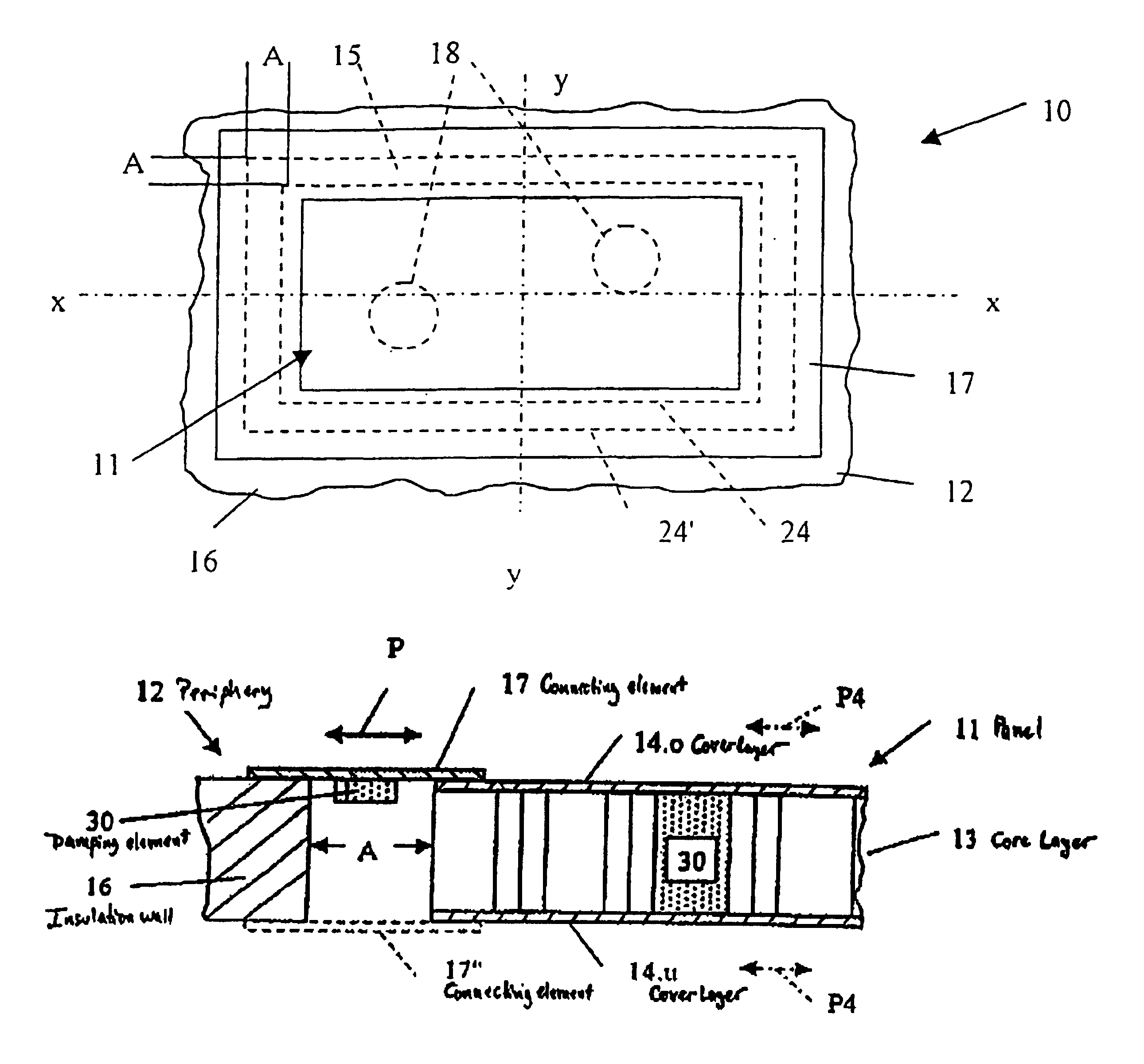
[0026]The invention will now be described in detail with reference to the Figures. FIG. 1 shows a sound reproduction device 10 in form of a panel loudspeaker operating according to the aforedescribed “bending wave principle.” The sound reproduction device 10 is formed by a panel 11 and a periphery 12.

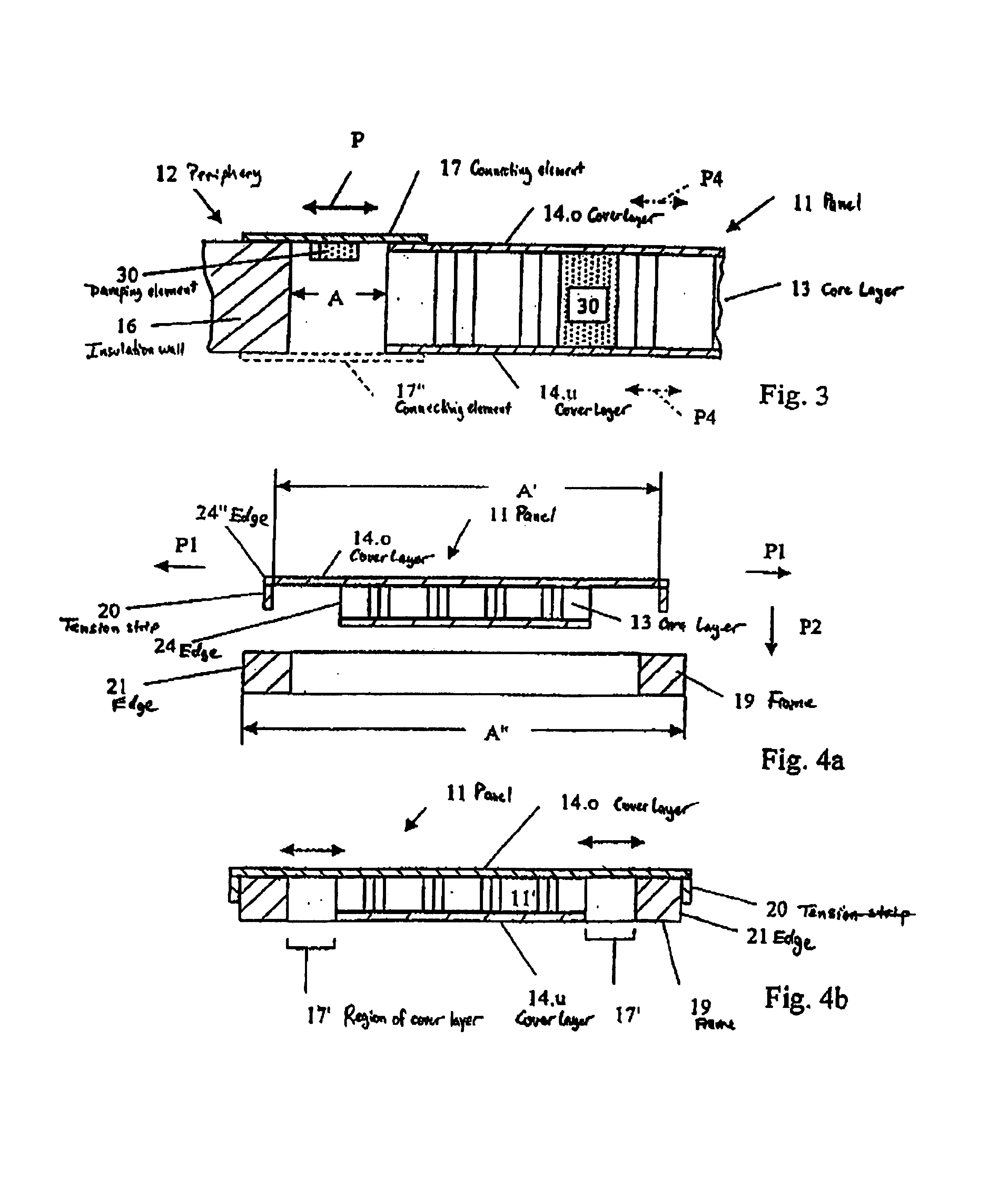
[0027]As seen in more detail in FIG. 3, the panel 11 is constructed as a sandwich structure which includes a core layer 13, which in the present example has a honeycomb structure, and thin cover layers 14.o, 14.u disposed on two opposing surfaces of the core layer 13.

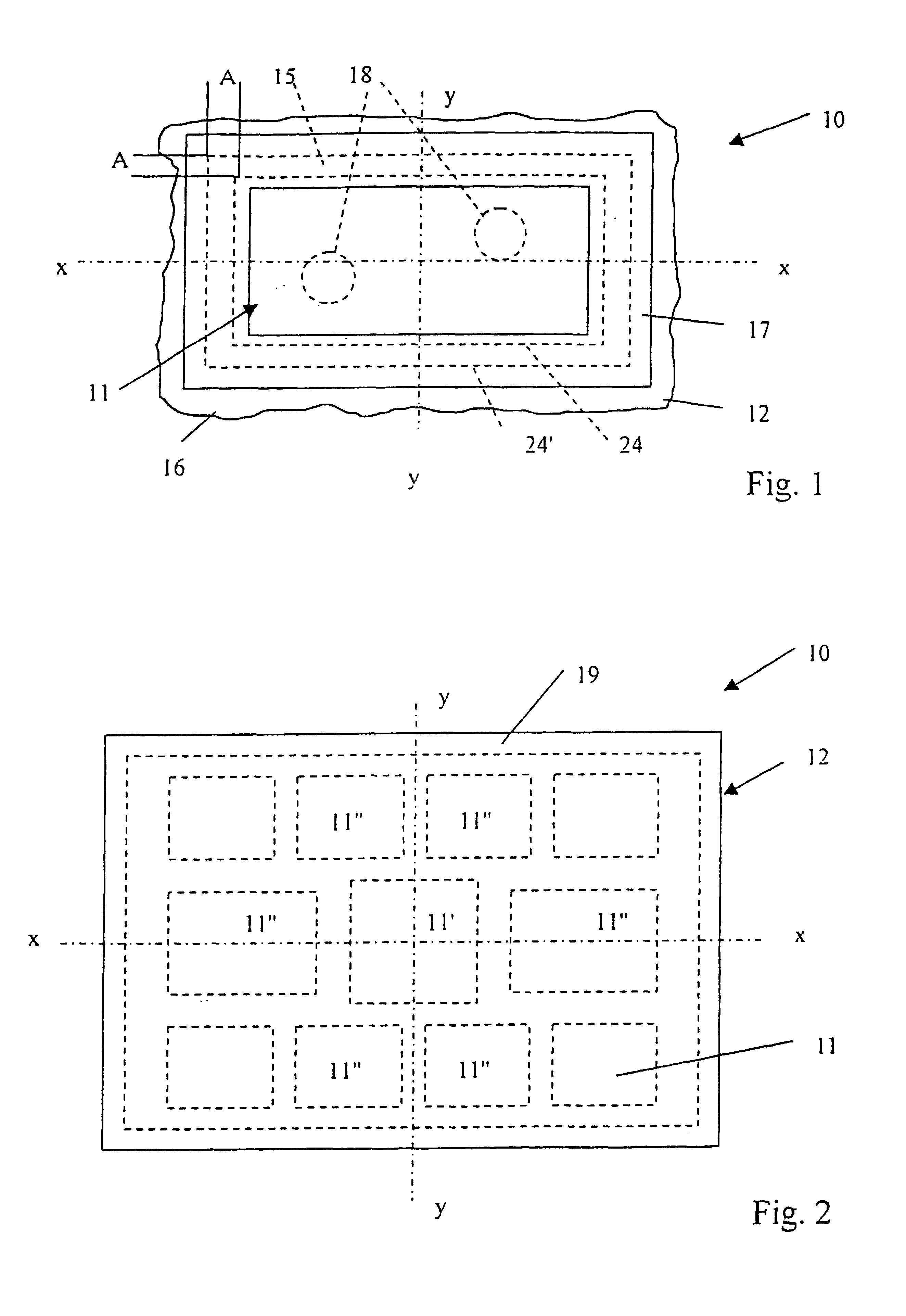
[0028]In the embodiment depicted in FIG. 1, the periphery 12 is formed by an installation wall with an opening 15. The panel 11 is inserted into this opening. The connection between the panel 11 and the periphery 12 formed by the installation wall 16 is implemented by connecting a connecting element 17 with the cover layers 14.o and the installation wall 16. As seen from FIG. 1, which depicts a top view of a panel loudspeak...


PUM


Abstract

The invention relates to so-called panel loudspeakers (11) working according to the multiresonance principle. Said loudspeakers are generally formed by a core layer (13) and at least one outer layer (14.o, 14.u). The outer layers (14.o, 14.u) are connected to the core layer (13). A periphery is also provided (12) enclosing the panel loudspeaker (11) at a lateral distance (A). The panel loudspeaker is connected to the periphery (12) by means of connecting elements (17, 17′). Although good reproduction results can be obtained in the mid and high audio frequencies with the panel loudspeakers (11) described above, undesired large panel surfaces are known to be required for good low frequency reproduction. When such panel surfaces are not used, the lowest panel resonances ensuring bass reproduction are shifted towards the midfrequencies. Hence, the invention aims at providing a panel loudspeaker (11) exhibiting improved acoustic reproduction in the low frequency range despite a relatively smaller panel surface. According to the invention, this is achieved in that the connecting elements (17 17′) are subjected to mechanical tension when they are connected to the periphery (12) resulting in supplementary particularly low frequency drum resonances in addition to the existing low frequency panel resonances, which can be modulated by the tension in the connecting elements (17, 17′).

Description

FIELD OF THE INVENTION[0001]The invention relates to panel loudspeakers and, more particularly, to improving the radiation characteristic of panel loudspeakers at low frequencies.BACKGROUND OF THE INVENTION[0002]Panel loudspeakers operating according to the multi-resonance principle are known in the art and frequently referred to as “distributed mode loudspeakers.” These devices are essentially formed of a flat panel and at least one drive system, wherein oscillations are introduced in the panel by supplying low frequency electrical audio signals to the drive system. The drive systems for these devices are formed of one or several of electromagnetic drivers (shakers), depending on the application. However, the drive systems can also include piezo-electric bending oscillators, either alone or in combination with the aforedescribed shakers.[0003]To properly operate panel loudspeakers, the loudspeakers are connected to a periphery using connecting elements. With this periphery, the ent...

Claims


Application Information

Patent Timeline
IPC IPC(8): H04R25/00H04R7/04H04R7/06H04R7/18
CPCH04R7/045H04R7/06H04R7/18H04R2307/201
Inventor BACHMANN, WOLFGANGKRUMP, GERHARDREGL, HANS-JURGENZIGANKI, ANDREAS
Owner HARMAN AUDIO ELECTRONICS SYST
Why Eureka
Try Eureka