
Method and apparatus for peripheral vehicle position calculation

a technology for vehicle position and calculation method, which is applied in the direction of navigation instruments, instruments, wireless communication, etc., can solve the problems of inability to communicate positional information with high accuracy in a limited communication band, and achieve the effect of reducing the amount of transmission data for positional information, high accuracy, and reducing the amount of information for communication among vehicles

Active Publication Date: 2007-06-26
ALPINE ELECTRONICS INC
View PDF4 Cites 21 Cited by
  • Summary
  • Abstract
  • Description
  • Claims
  • Application Information

AI Technical Summary

Benefits of technology

This approach reduces the amount of information transmitted, enabling accurate real-time monitoring and display of peripheral vehicle positions on navigation maps, while minimizing communication congestion and ensuring timely warnings for approaching vehicles.

Problems solved by technology

In other words, positional information cannot be communicated with high accuracy in a limited communication band.
However, this is not possible under the current communication scheme.

Method used


Image

  • Method and apparatus for peripheral vehicle position calculation
  • Method and apparatus for peripheral vehicle position calculation
  • Method and apparatus for peripheral vehicle position calculation

Examples


example

[0038]Display Example

[0039]FIG. 5 shows an application according to an embodiment of the present invention and shows an example in which a current vehicle position mark CMK and peripheral vehicles position marks M1 to Mn representing positions of peripheral vehicles are displayed on a map image MAPI. Such applications for example, warn against approaching vehicles and the like.

[0040]Broadcast Processing

[0041]FIG. 6 is a flowchart showing broadcast control processing in the vehicle-mounted device.

[0042]The signal processing unit 15 acquires the speed and the direction of the current vehicle from the navigation unit 20 (act S101). The signal processing unit 15 determines whether the amount of speed change exceeds a predetermined amount of speed change (for example, ±5 km / h) (act S102) and determines whether the amount of average direction change exceeds a predetermined amount of direction change (for example, ±3°) (act S103). If the amount of speed change is less than or equal to the ...

working example

[0062

[0063]For comparing with the comparative example, data is sent every 0.1 seconds. The second definition data is sent once for every five times, and the first definition data is sent four times for every five times.

[0064]14 bytes×8 bits×8 times / sec=896 bps / vehicle

[0065]22 bytes×8 bits×2 times / sec=352 bps / vehicle

[0066](896+352) bps×300 vehicles=374,000 bps=374 kbps

[0067]As described above, the total amount of transmission data can be significantly reduced.

[0068]Adjusting a transmission interval in accordance with the vehicle speed can further reduce congestion in a communication band. For example, referring to FIG. 8B, when the vehicle speed is 20 km / h, it is sufficient for data to be sent with 0.3-second intervals for maintaining a position error of 2 m or less. Also, when the vehicle speed is 30 km / h, it is sufficient for data to be sent with 0.2-second intervals.

[0069]Usage Example of Peripheral Vehicle Positional Information

[0070]Although an example in which positions of peri...


PUM


Abstract

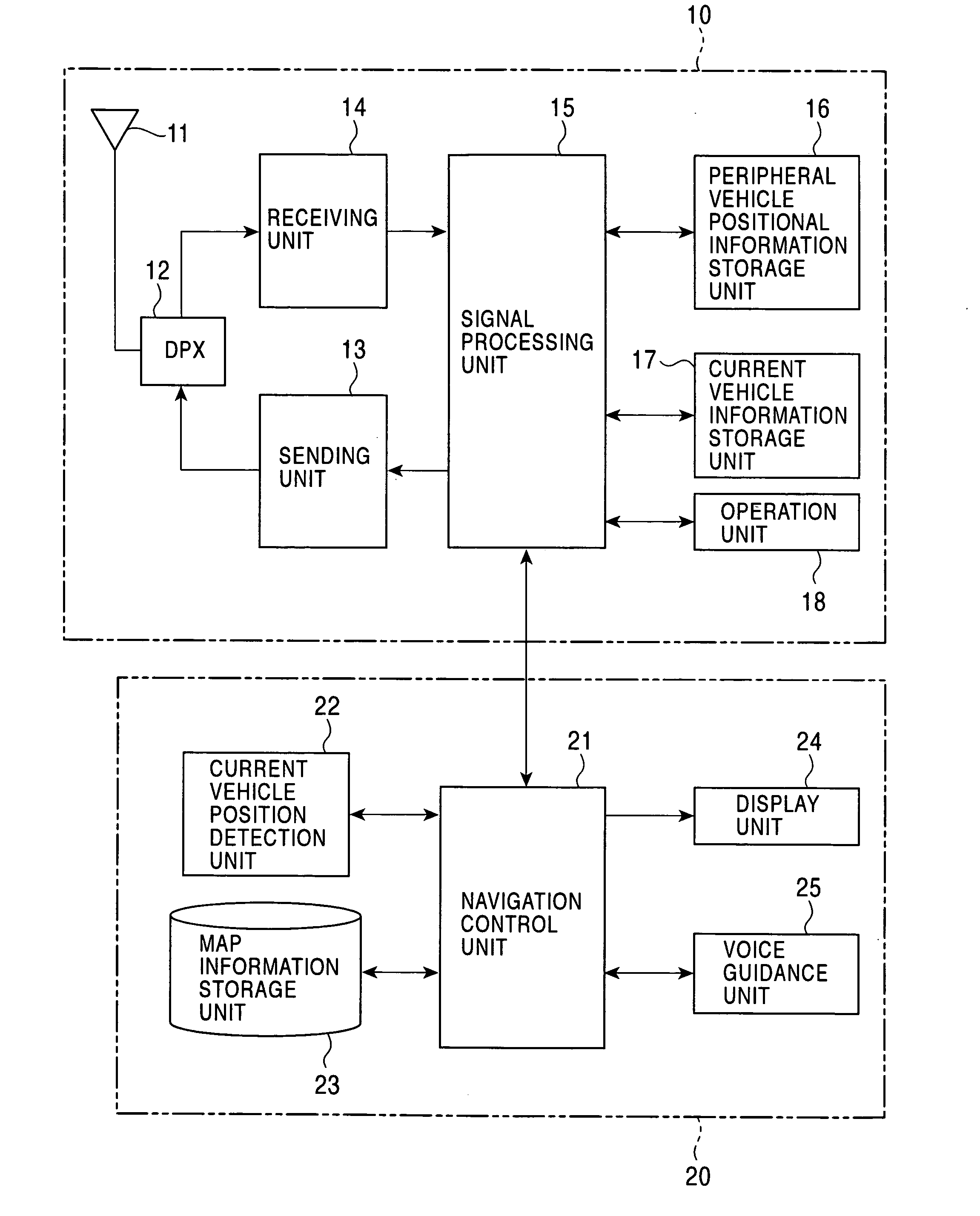
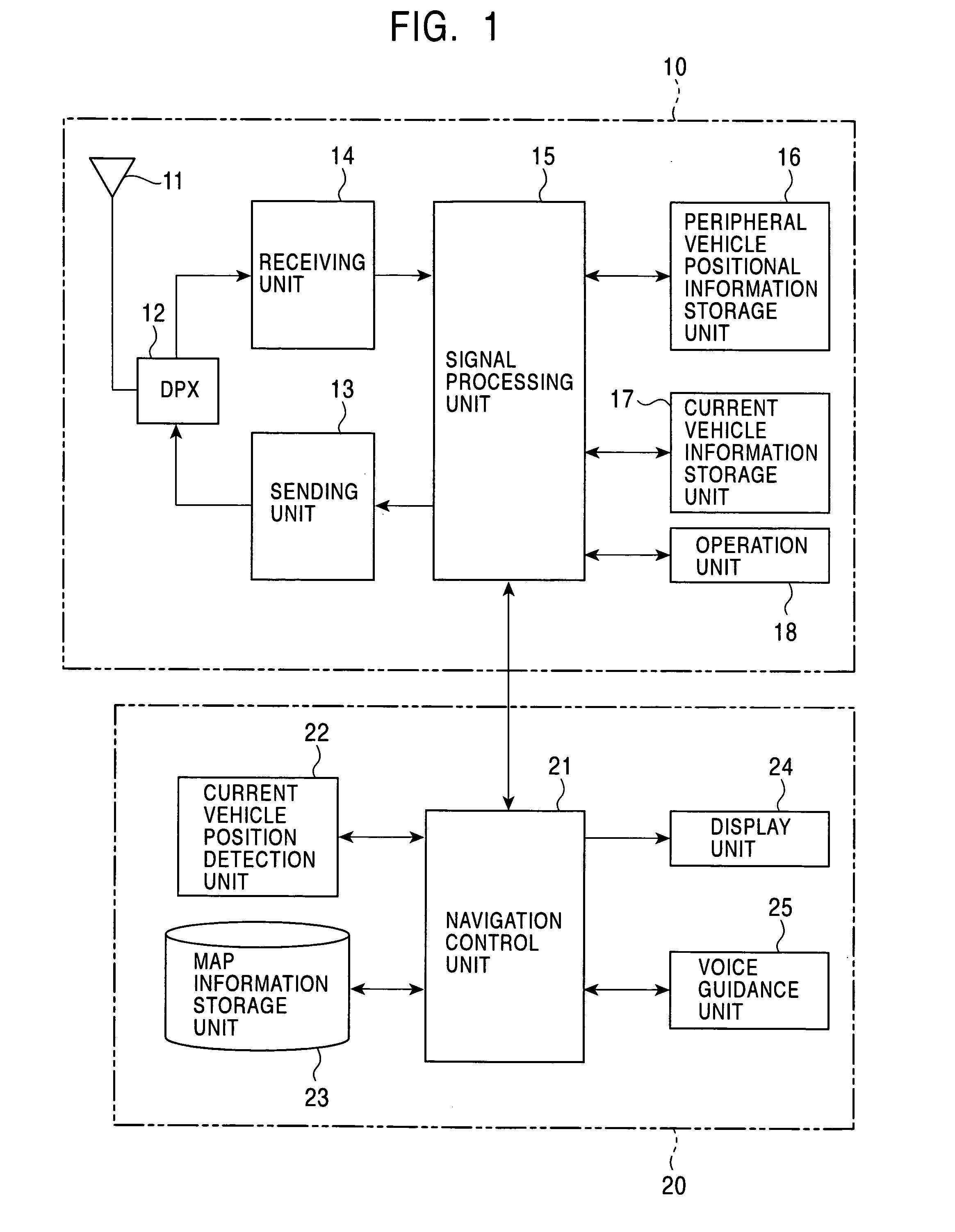
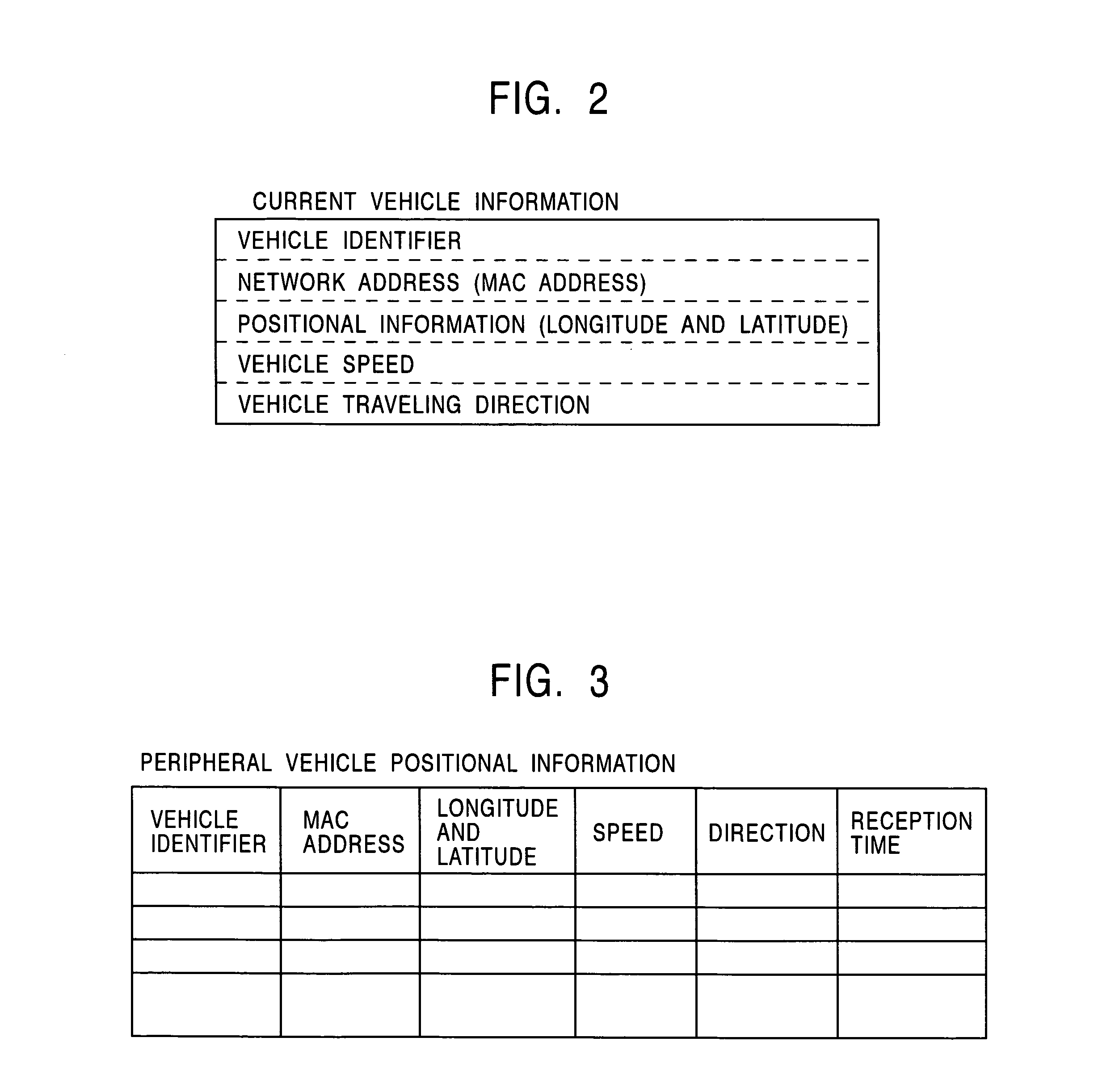
A signal processing unit of a radio communication section of a vehicle-mounted device mounted on a vehicle broadcasts first sets of data, each set of data including a vehicle speed and a traveling direction of the vehicle at a predetermined period when the vehicle changes the vehicle speed or the traveling direction. The signal processing unit broadcasts second sets of data including the current vehicle position, the vehicle speed, and the traveling direction of the vehicle at predetermined timing. When receiving the first data and the second data from a peripheral vehicle, the signal processing unit calculates a position of the peripheral vehicle in accordance with the first and second sets of data.

Description

BACKGROUND OF THE INVENTION[0001]1. Field of the Invention[0002]The present invention relates to vehicle-mounted devices and peripheral vehicle position calculation methods, and more particularly, to a vehicle-mounted device and a peripheral vehicle position calculation method for calculating positions of peripheral vehicles on the basis of information received from the peripheral vehicles via inter-vehicle communication and for performing predetermined processing based on the positions of the peripheral vehicles.[0003]2. Description of the Related Art[0004]Development in communication technologies has enabled communication among moving objects, such as vehicles, (referred to as inter-vehicle communication). For example, Bluetooth™, radio local area networks (LANs), and other means are available as inter-vehicle communication means.[0005]Bluetooth™ is a radio link technology intended to be used as a cable replacement between electronic devices of a moving body and a fixed apparatus ...

Claims


Application Information

Patent Timeline
Patent Type & Authority Patents(United States)
IPC IPC(8): G01C21/00G01C21/26G01S5/00G08G1/09G08G1/0967G08G1/0969H04B7/26H04W64/00
CPCG01C21/26G01S5/0027G08G1/096716G08G1/096758G08G1/096791
Inventor WATANABE, HISAYUKI
Owner ALPINE ELECTRONICS INC
Learn More