Tracking cells for a memory system

a memory system and tracking cell technology, applied in the field of reading memory devices, can solve the problems of limiting the endurance of prior flash memory devices, affecting the performance of flash memory devices, and prone to damag

Inactive Publication Date: 2007-06-26
SANDISK TECH LLC
View PDF103 Cites 386 Cited by
  • Summary
  • Abstract
  • Description
  • Claims
  • Application Information

AI Technical Summary

Benefits of technology

[0017]These and other objects and advantages of the present invention will appear more clearly from the following description in which the preferred embodiment of the invention has been set forth in conjunction with the drawings.

Problems solved by technology

With use, defects tend to build up in the memory device and may eventually render the device unreliable.
One physical phenomenon limiting the endurance of prior flash memory devices is the trapping of electrons in the active dielectric between the floating gate and the substrate.
If program / erase cycling is continued, the device may eventually experience catastrophic failure.
This problem is even more critical if multi-state memory is implemented, since more accurate placement of the threshold voltage is demanded.
A second problem pertains to charge retention on the floating gate.
For example, negative charge on the floating gate tends to diminish somewhat through leakage over a period of time.
A third problem is that the program / erase cycles may not be performed evenly for the cells in the memory device.
Such uneven programming and erasing causes non-uniform stress conditions for the cells in a particular sector.
Non-uniformity of the program / erase cycling histories can result in a wider distribution of threshold voltages for any particular given state.
In addition to widening the threshold distributions, certain cells may reach closure of the voltage window, device failure or charge retention issues earlier than others.

Method used


Image

  • Tracking cells for a memory system
  • Tracking cells for a memory system
  • Tracking cells for a memory system

Examples


Embodiment Construction

I. Memory System

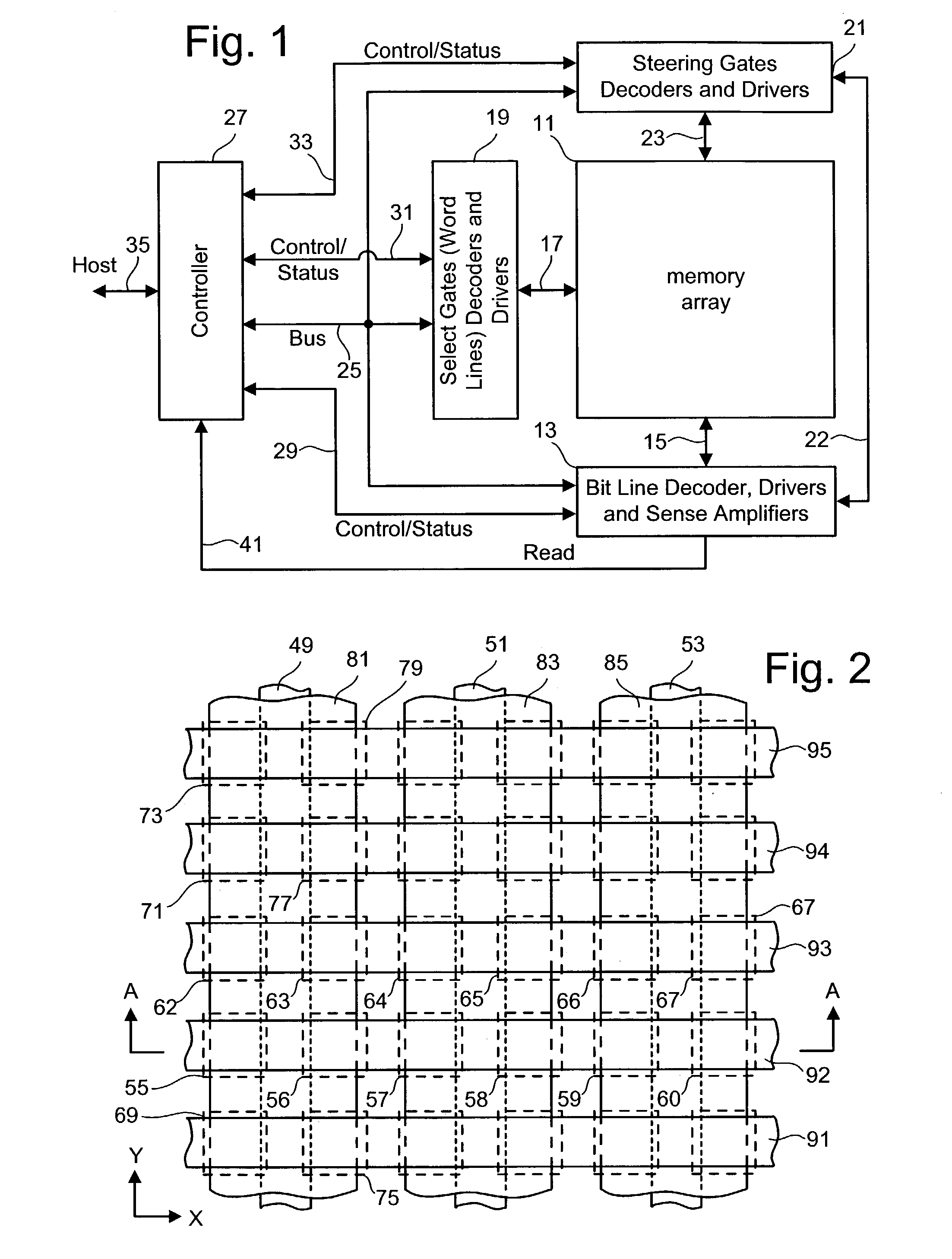
[0033]An example memory system incorporating the various aspects of the present invention is generally illustrated in the block diagram of FIG. 1. Architectures other than that of FIG. 1 can also be used with the present invention. A large number of individually addressable memory cells 11 are arranged in an array of rows and columns. Bit lines, which extend along columns of array 11, are electrically connected with bit line decoder, driver and sense amplifiers circuit 13 through lines 15. Word lines, which extend along rows of array 11, are electrically connected through lines 17 to word line decoders and drivers circuit 19. Steering gates, which extend along columns of memory cells in array 11, are electrically connected to steering gate decoders and drivers circuit 21 through lines 23. Each of the circuits 13, 19 and 21 receives addresses from controller 27 via bus 25. The decoder and driving circuits 13,19 and 21 are also connected to controller 27 over respectiv...


PUM


Abstract

Tracking cells are used in a memory system to improve the read process. The tracking cells can provide an indication of the quality of the data and can be used as part of a data recovery operation if there is an error. The tracking cells provide a means to adjust the read parameters to optimum levels in order to reflect the current conditions of the memory system. Additionally, some memory systems that use multi-state memory cells will apply rotation data schemes to minimize wear. The rotation scheme can be encoded in the tracking cells based on the states of multiple tracking cells, which is decoded upon reading.

Description

BACKGROUND OF THE INVENTION[0001]1. Field of the Invention[0002]The present invention is directed to technology for reading memory devices.[0003]2. Description of the Related Art[0004]Semiconductor memory devices have become more popular for use in various electronic devices. For example, non-volatile semiconductor memory is used in cellular telephones, digital cameras, personal digital assistants, mobile computing devices, non-mobile computing devices and other devices. Electrical Erasable Programmable Read Only Memory (EEPROM) and flash memory are among the most popular non-volatile semiconductor memories.[0005]Both EEPROM and flash memory utilize a floating gate that is positioned above and insulated from a channel region in a semiconductor substrate. The floating gate is positioned between source and drain regions. A control gate is provided over and insulated from the floating gate. The threshold voltage of the transistors is controlled by the amount of charge that is retained ...

Claims


Application Information

Patent Timeline
Patent Type & Authority Patents(United States)
IPC IPC(8): G06F12/00G11C11/00G11C11/409G11C11/56G11C16/26G11C16/34
CPCG11C16/26G11C16/349G11C11/5621G11C11/56G11C16/00
Inventor GUTERMAN, DANIEL C.GROSS, STEPHEN J.KHALID, SHAHZADGONGWER, GEOFFREY S.
Owner SANDISK TECH LLC
Why Eureka
Try Eureka