Seal arrangement
- Summary
- Abstract
- Description
- Claims
- Application Information
AI Technical Summary
Benefits of technology
Problems solved by technology
Method used
Image

Examples
first embodiment
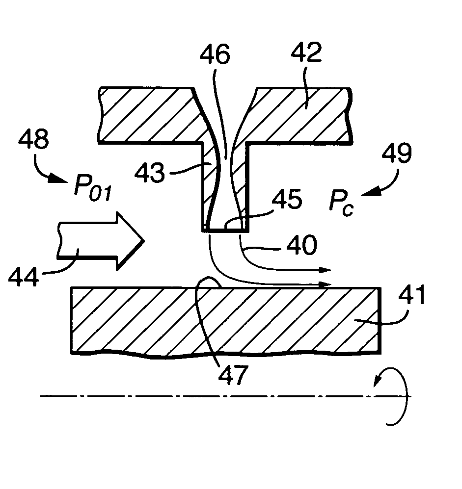
[0049]FIG. 4 illustrates a seal arrangement as a schematic cross-section. Thus, the seal arrangement comprises a rotating component 41 and a housing 42 from which a fin 43 projects towards the component 41. A leakage path occurs in the direction of arrow head 44. A jet of fluid 40 is projected laterally across the gap between an outlet 45 in a slot 46 formed in the fin 43 and an opposed part 47 of the rotating component 41. It will be appreciated that in use there is a pressure gradient between an upstream side 48 and a downstream side 49 of the arrangement. The fin 43 acts as a constriction in the manner of a conventional labyrinth seal.
[0050]One or more slots 46 are incorporated within the fin 43 such that there is a projected fluid flow 40 which may be initially perpendicular to the leakage path 44 but which is turned by the leakage flow 44 due to the pressure gradient from high pressure upstream side 48 and a low pressure downstream side 49 along the rotor surface. In such circu...
third embodiment
[0056]FIG. 8 illustrates a seal arrangement in accordance with the present invention. Thus, a rotating component 81 is associated with a housing 82 such that there is a fin 83 extending across a duct spacing between them to act as a constriction to a leakage flow 84. However, in comparison with previous embodiments, a slot nozzle 86 is not located within the fin 83 but rather within a flat surface. In such circumstances, a fluid flow 80 again acts to form a fluid sheet as a sealing barrier across the leakage gap between an end surface 87 of the fin 83 and an opposed flat surface, in the depicted embodiment, in the rotating component 81. As indicated previously, providing a fin 83 with a sharp edge causes annular leakage flow jet lift off which in itself reduces the freely available leakage gap compared to the physical clearance between the rotating component 81 and end surface 87. Thus, the fluid flow 80 in the form of flow sheets will augment that leakage gap width reduction in ord...
ninth embodiment
[0064]All the previous embodiments described above with regard to the present invention have provided a slot nozzle in which there is a convergent-divergent profile. FIG. 14 illustrates a seal arrangement in accordance with the present invention in which a simple convergent slot nozzle 146 incorporated within a fin 143 is provided such that a fluid flow 140 projected from an outlet 145 of that slot nozzle 146 is presented in order to obstruct a leakage flow 144. As previously, the leakage flow 144 is stimulated by pressure differentials between a high pressure side 148 and a low pressure side 149. The fin 143 acts as a physical constriction to that flow 144 and also through leakage flow jet contraction effect about the sharp edge of that fin 143 acts to restrict the available leakage gap width. The fluid flow 140 augments that sealing function by projection towards a surface 147 of the rotating component 141. As previously, if the pressure differential between the high pressure side...
PUM
 Abstract
Description
Claims
Application Information