Rotary electric machine with stator outer surface designed to enhance heat dissipation

a technology of rotary electric machines and stators, which is applied in the direction of windings, cooling/ventilation arrangements, and magnetic circuit shapes/forms/construction, etc. it can solve the problems of increasing the number of piping systems, increasing the density and complexity of machine or device arrangement in the engine compartment, and reducing the gap between the claws of the rotor core. , to achieve the effect of increasing the power output of the rotary electric machine, reducing the leakage of magneti

Inactive Publication Date: 2010-09-21
DENSO CORP
View PDF28 Cites 4 Cited by
  • Summary
  • Abstract
  • Description
  • Claims
  • Application Information

AI Technical Summary

Benefits of technology

[0014]It is, therefore, an object of the present invention to provide a rotary electric machine which has an improved structure that ensures excellent cooling performance of the rotary electric machine while making the rotary electric machine compact.
[0035]In this case, leakage of magnetic flux from the gaps between the claws of the rotor core can be reduced, thereby increasing the power output of the rotary electric machine.

Problems solved by technology

Consequently, the space available for installation of an automotive alternator in the engine compartments has accordingly become small.
However, at the same time, providing the hollow space for the flow of the coolant makes the automotive alternator redundant.
Further, a piping system is necessary for supplying the coolant to the automotive alternator from, for example, an engine radiator; the piping system makes the arrangement of machines or devices in the engine compartment denser and more complex.

Method used


Image

  • Rotary electric machine with stator outer surface designed to enhance heat dissipation
  • Rotary electric machine with stator outer surface designed to enhance heat dissipation
  • Rotary electric machine with stator outer surface designed to enhance heat dissipation

Examples


Embodiment Construction

[0044]The preferred embodiment of the present invention will be described hereinafter with reference to FIGS. 1-4.

[0045]It should be noted that, for the sake of clarity and understanding, identical components having identical functions have been marked with the same reference numerals in each of the figures.

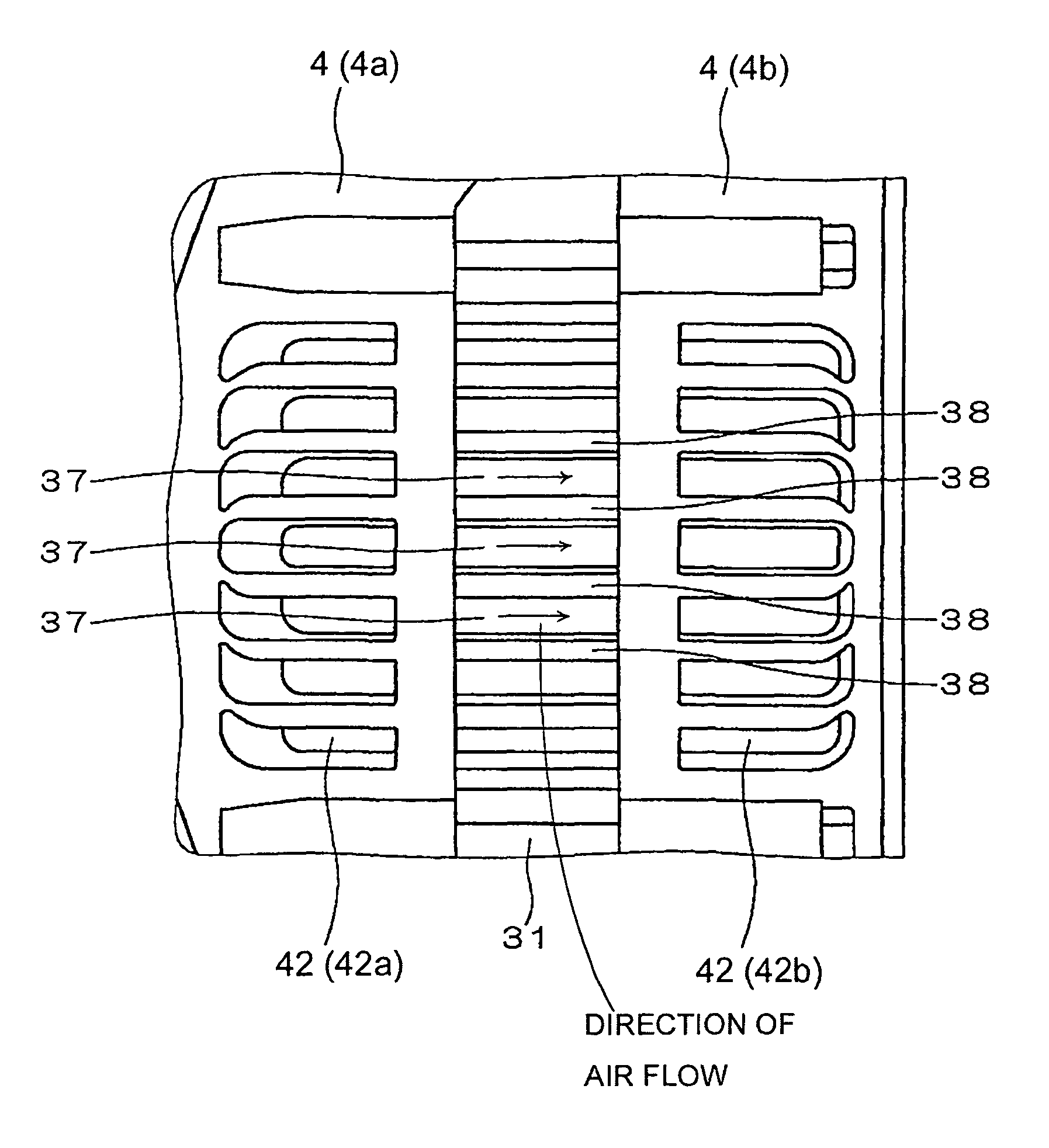
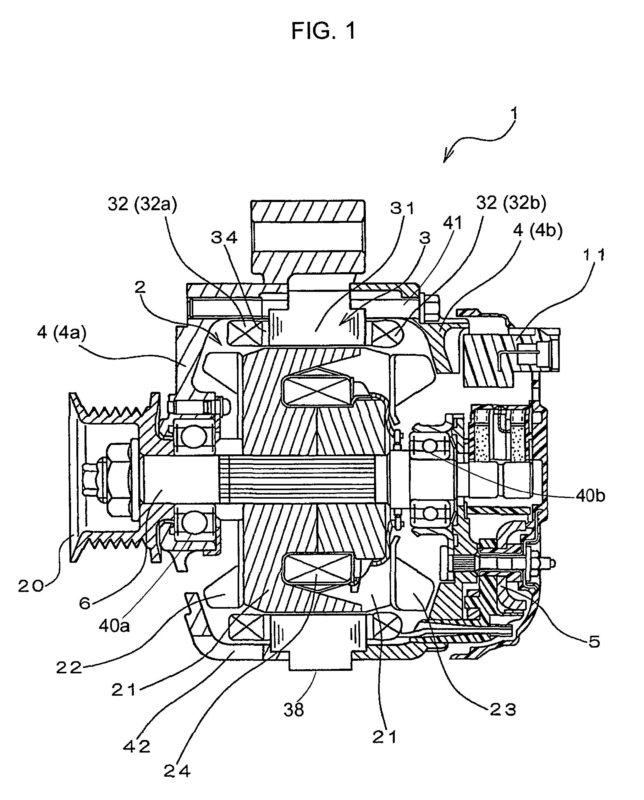
[0046]FIG. 1 shows the overall structure of an automotive alternator 1 according to an embodiment of the present invention.

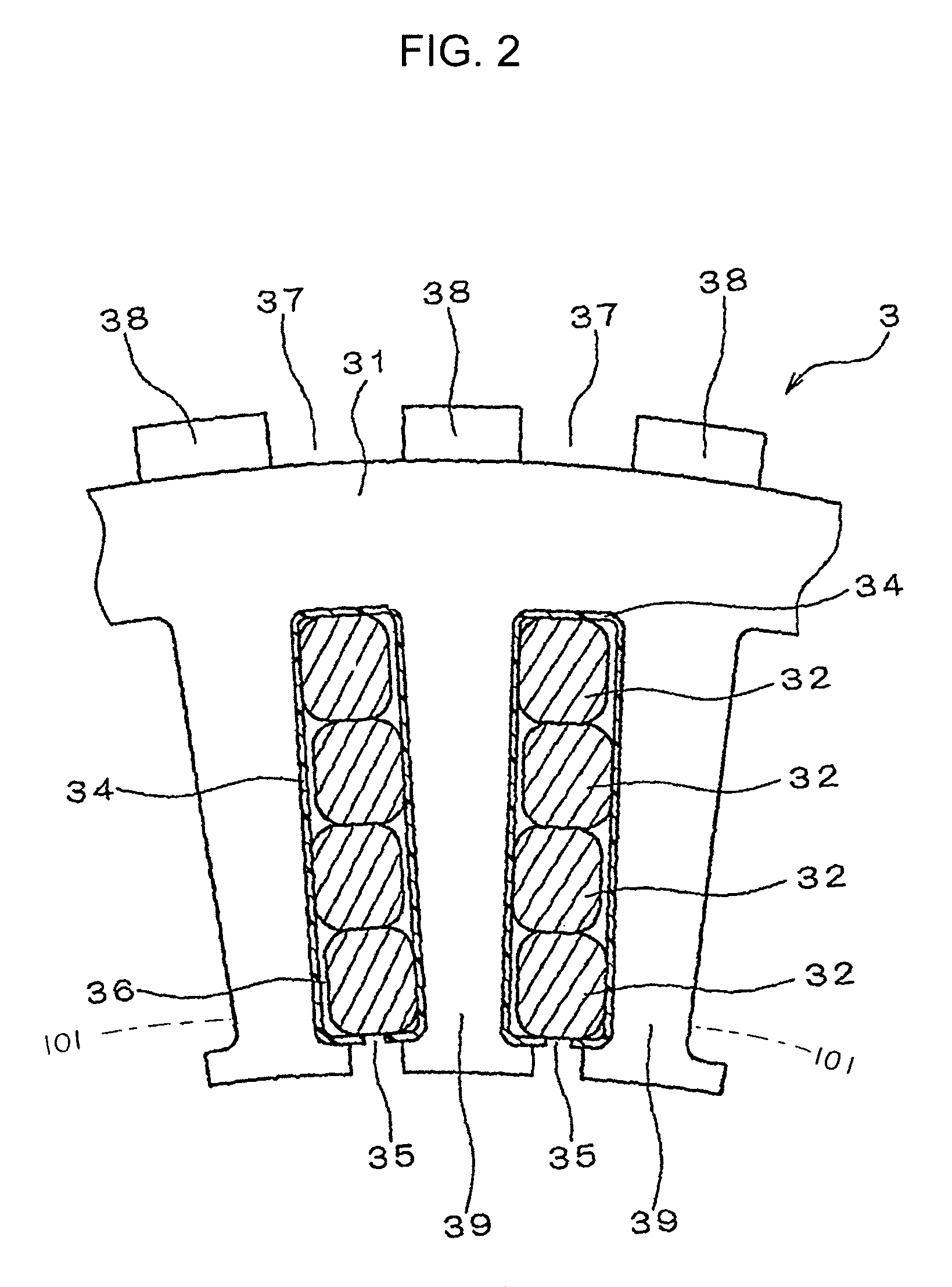
[0047]As shown in FIG. 1, the automotive alternator 1 includes a rotor 2, a stator 3, a frame 4, a rectifier 5, a voltage regulator 11, and a pulley 20.

[0048]The rotor 2 works to create a rotating magnetic field. The rotor 2 includes a rotary shaft 6, a lundell-type rotor core 21 that has a plurality of claws and is mounted on the rotary shaft 6, a pair of cooling fans 22 and 23, and a field winding 24 wound around the rotor core 21.

[0049]The cooling fan 22 is fixed to the pulley-side axial end of the rotor core 21 by welding. On the other hand, the cooling f...


PUM


Abstract

According to the present invention, a rotary electric machine includes a rotor with a rotary shaft, a stator surrounding an outer periphery of the rotor, and a frame supporting the rotor and the stator. Further, the stator has an outer surface at least part of which is exposed to outside of the frame, and a plurality of protrusions and recesses are formed on the exposed part of the outer surface of the stator, so as to enhance dissipation of heat generated by operation of the rotary electric machine. According to a further implementation of the present invention, the rotor includes at least one fan that works to create air flow, and the protrusions and the recesses are so formed that the recesses make up air flow paths, along which the air flow created by the fan passes over the outer surface of the stator, thereby cooling the outer surface.

Description

CROSS-REFERENCE TO RELATED APPLICATION[0001]This application claims priority from Japanese Patent Application No. 2005-207101, filed on Jul. 15, 2005, the content of which is hereby incorporated by reference into this application.BACKGROUND OF THE INVENTION[0002]1 Technical Field of the Invention[0003]The present invention relates generally to rotary electric machines. More particularly, the invention relates to a rotary electric machine for a vehicle (e.g., an automotive alternator), which includes a stator that has an outer surface designed to enhance the dissipation of heat generated by operation of the rotary electric machine.[0004]2 Description of the Related Art[0005]In recent years, engine compartments in vehicles have been increasingly required to be small, so as to meet the requirements of adopting a slant-nose design to reduce the vehicle running resistance and securing a more sufficient space in the vehicle compartments. Consequently, the space available for installation ...

Claims


Application Information

Patent Timeline
Patent Type & Authority Patents(United States)
IPC IPC(8): H02K9/00
CPCH02K1/20H02K9/06H02K9/16
Inventor NAKAMURA, SHIGENOBUKONDOH, SEIJI
Owner DENSO CORP
Why Eureka
Try Eureka