Method and apparatus for stent deployment with enhanced delivery of bioactive agents

a bioactive agent and stent technology, applied in the field of stents, can solve the problems of lack of bioactive or penetration agents for stents, and achieve the effect of enhancing the penetration rate of bioactive agents

Inactive Publication Date: 2007-07-03
BOARD OF RGT THE UNIV OF TEXAS SYST
View PDF25 Cites 65 Cited by
  • Summary
  • Abstract
  • Description
  • Claims
  • Application Information

AI Technical Summary

Benefits of technology

[0009]In one preferred embodiment, the stents of the present invention do not change shape after deployment. In another preferred embodiment, the stents of the present invention have an expanded or deployed state and non-expanded or non-deployed state. In the non-expanded or non-deployed state, the stent has a smaller dimension compared to the stent in its expanded or deployed state. The dimension can be a cross-sectional dimension, a length dimension or a combination thereof. When the stent is in its non-expanded or non-deployed state, the non-recessed regions protrude or extend above and protect the compositions and / or structures contained in the recessed regions.
[0010]Moreover, the non-recessed regions are designed to deform, expand and / or elongate to a lesser extent during stent expansion or deployment than the recessed regions. On the other hand, the recessed regions are designed to deform, expand, elongate and / or flatten during deployment. The deformation of the recessed regions during stent deployment can cause the stent to assume a final contour, where the recessed regions are substantially continuous with the non-recessed regions so the all portion of the deployed stent contact the tissue site or surface to approximately the same extent. Alternatively, the stent can deploy so that the recessed regions extend above the non-recessed regions contacting the tissue site or surface to a greater extent than the non-recessed regions. This deformation serves to bring the compositions, structures or combinations or mixtures thereof situated in the recessed regions into close proximity or direct contact with the tissue surface such as the interior of a vessel or the tissue within a tissue site at the site of deployment.
[0012]The present invention also provides a method for treating, expanding or supporting a vessel or other tissue site to achieve a given prophylactic or therapeutic result including the step of positioning a stent of the present invention at a desired site or position in an interior of a vessel or within a tissue in the body of an animal. Once properly positioned, the stent is expanded or deployed forcing the recessed regions to deform, expand, elongate and / or flatten. The deformation of the stent can cause the non-recessed regions and recessed regions to be brought into close proximity or direct contact with the tissue site exposing the tissue site to the compositions and / or structures contained within the recessed regions. Alternatively, the deformation can cause the recessed regions to protrude or extent above the non-recessed regions so that the compositions and / or structures contained within the recessed regions contact the tissue site to a greater extent than the non-recessed region. An ordinary artisan should realized that in this embodiment, the recessed regions in the non-deployed state have become the non-recessed regions of the deployed states and vis-a-versa. The contact between the stent recessed regions and the tissue site produce a therapeutic and / or prophylactic effect. If the stent is bioerodible, an additional step will be the gradual removal or decomposition of stent itself.
[0013]The present invention also provides a method for treating, expanding or supporting a tissue site to achieve a given prophylactic and / or therapeutic result which includes positioning a stent of the present invention at a desired site or position in a tissue of the body of an animal including a human. Once properly positioned, the stent is deployed, thereby forcing the recessed regions to deform, expand, elongate and / or flatten. The deformation of the stent can cause the non-recessed regions and recessed regions to be brought into close proximity or direct contact with the tissue site exposing the tissue site to the compositions and / or structures contained within the recessed regions. Alternatively, the deformation can cause the recessed regions to protrude or extent above the non-recessed regions so that the compositions and / or structures contained within the recessed regions contact the tissue site to a greater extent than the non-recessed region. An ordinary artisan should realize that in this embodiment, the recessed regions in the non-deployed state have become the non-recessed regions of the deployed states and vis-a-versa. The contact between the stent recessed regions and the tissue site produce a therapeutic and / or prophylactic effect. If the stent is bioerodible, an additional step will be the gradual removal or decomposition of stent itself.

Problems solved by technology

However, these stents lack bioactive or penetrating agents to assist in vessel or tissue healing or deposit digestion, and / or mechanisms for the protection of bioactive or penetrating agents during stent deployment and positioning.

Method used


Image

  • Method and apparatus for stent deployment with enhanced delivery of bioactive agents
  • Method and apparatus for stent deployment with enhanced delivery of bioactive agents
  • Method and apparatus for stent deployment with enhanced delivery of bioactive agents

Examples


first embodiment

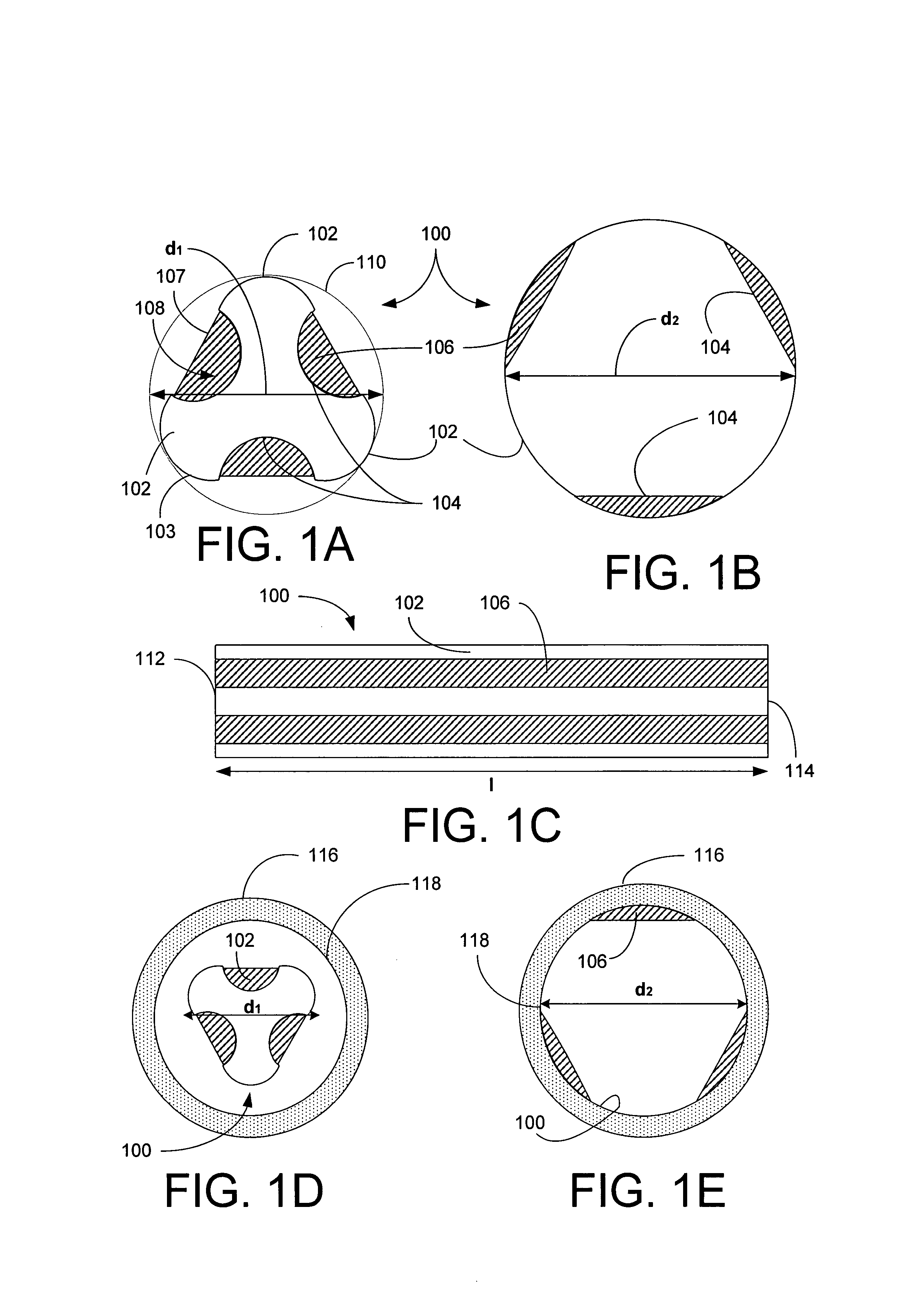
[0102]Referring now to FIGS. 1A–B, a stent 100 of the present invention is shown in cross-section to have a generally triangular cross-section in its un-deployed state and a generally circular cross-section in its deployed state, respectively. The stent 100 includes three convex arcuate, non-recessed regions 102 and three concave recessed regions 104, where the regions 102 and 104 regions alternate. The stent 100 also includes a bioactive composition 106 deposited in protected zones 108 located in the recessed regions 104, where the composition 106 outer surface 107 is below an outer surface 103 of the non-recessed areas 102. The stent's cross-sectional dimension in its undeployed state, as shown in FIG. 1A, can be inscribed in a first circle 110 having a first diameter d1 and after deployed, the stent assumes a substantially circular contour having a diameter d2, where d2 is greater than or equal to d1.

[0103]Referring now to FIG. 1C, the stent 100 is shown in a side view where the ...

second embodiment

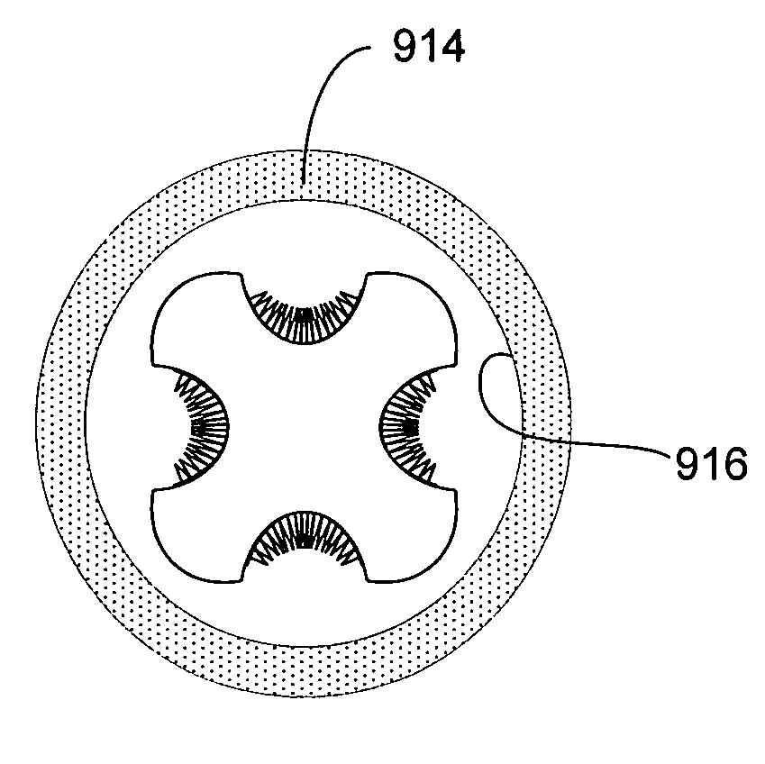
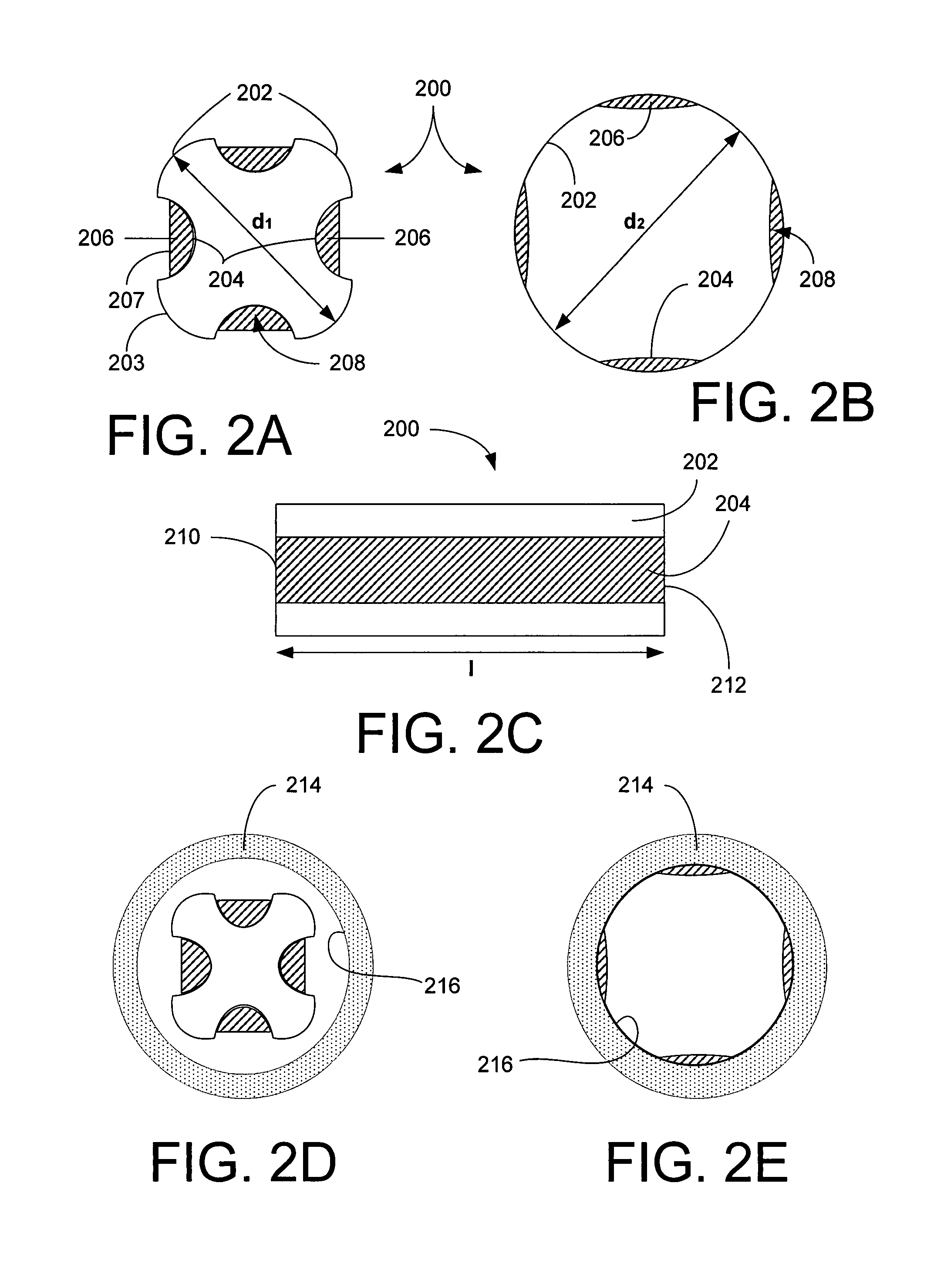
[0105]Referring now to FIGS. 2A–B, a stent 200 of the present invention is shown in cross-section to have a generally square cross-section in its un-deployed state and a generally circular cross-section in its deployed state, respectively. The stent 200 includes four substantially rigid arcuate non-recessed regions 202 and four deformable, concave recessed regions 204 interposed between each pair of non-recessed regions 202 so that the regions 202 and 204 alternate. The stent 200 also includes a bioactive composition 206 deposited in protective zones 208 associated with each recessed region 204. Again, the composition 206 has an outer surface 207 that is below an outer surface 203 of the non-recessed areas 202.

[0106]In its undeployed state, the stent 200, as shown in FIG. 2A, has a first diameter or cross-sectional dimension of d1 and after deployed, the stent 200 assumes a substantially circular contour having a diameter d2 in its deployed state, where d2 is greater than or equal t...

third embodiment

[0109]Referring now to FIGS. 3A–B, a stent 300 of the present invention is shown in cross-section to have a generally pentagonal (5-sided) cross-section in its un-deployed state and a generally circular cross-section in its deployed state, respectively. The stent 300 includes five substantially rigid arcuate non-recessed regions 302 and five deformable, recessed regions 304 interposed between each pair of non-recessed regions 302 so that the regions 302 and 304 alternate. The stent 300 also includes a bioactive composition 306 deposited in protected zones 308 associated with each recessed region 304. Again, the composition 306 has an outer surface 307 that is below an outer surface 303 of the non-recessed areas 302. The stent 300 has an undeployed or first diameter or cross-sectional dimension (largest cross-sectional dimension) d1 and a deployed or second diameter or cross-sectional dimension (largest cross-sectional dimension) d2, where d2 is greater than or equal to d1.

[0110]Refe...


PUM


Abstract

A stent for use in animals including humans is disclosed which includes unprotected and protected regions, each protected regions including a bioactive or biopenetrating agent containing therein where the protected regions are protected by the unprotected regions when the stent is in its undeployed state which has a smaller cross-sectional dimension than the stent in its deployed state. And when the stent is in its deployed state the bioactive or biopenetrating agent(s) are brought into direct and intimate contact with a tissue or interior of a blood vessel of an animal including a human.

Description

RELATED APPLICATIONS[0001]This application is a 35 U.S.C. § 371 National Phase Application of PCT / US02 / 05782 filed 27 Feb. 2002, which claims provisional priority to U.S. Provisional Patent Application Ser. No. 60 / 273,592 filed 6 Mar. 2001.BACKGROUND OF THE INVENTION[0002]1. Field of the Invention[0003]This invention relates to a stent including indentations having either bioactive agents and / or penetrating structures and / or agents therein or thereon where the indentations protect the agents or structures during stent positioning and where the agents or structures are brought into close proximity to or in contact with a vessel's interior or tissue during stent deployment.[0004]More particularly, this invention relates to a corrugated stent having recessed regions containing bioactive or penetration agents or structures and non-recessed regions, where the agents are protected in the recessed regions. Preferably, the stent undergo a volumeric expansion after deployment, that brings th...

Claims


Application Information

Patent Timeline
Patent Type & Authority Patents(United States)
IPC IPC(8): A61F2/06A61F2/00A61F2/82
CPCA61F2/82A61F2250/0067
Inventor FELDMAN, MARC D.BAILEY, STEPHEN R.AGRAWAL, C. MAULIATHANASIOU, KYRIACOS A.
Owner BOARD OF RGT THE UNIV OF TEXAS SYST
Why Eureka
Try Eureka