Color gamut mapping using a cost function

a color gamut mapping and function technology, applied in the field of digital imaging, can solve the problems of affecting the color gamut mapping accuracy, the inability to create the output color imaging device, and the combination of colors can produce visible patterns with undesirable grainy appearance, etc., to achieve accurate color calibration, reduce color gamut boundaries, and high quality

Inactive Publication Date: 2007-07-03
EASTMAN KODAK CO
View PDF39 Cites 30 Cited by
  • Summary
  • Abstract
  • Description
  • Claims
  • Application Information

AI Technical Summary

Benefits of technology

[0023]By using a cost function to create a reduced color gamut boundary used in preparing a digital image for a digital printer in accordance with the present invention, high quality digital images that are free of the above mentioned artifacts are provided. The present invention provides a way of creating a color gamut boundary that simultaneously provides accurate color calibration and total colorant amount limiting for a digital printer, while minimizing the appearance of undesirable graininess or noise. The present invention provides for a substantial improvement over the prior art in that it provides these benefits for multilevel printers in which the colorant amount may not be linear or monotonic with digital code value.

Problems solved by technology

CMYK printers in particular pose a challenge when creating a color transform.
Thus, DICS values that fall inside of this color gamut boundary are capable of being created by the output color imaging device, and DICS values that fall outside of this color gamut boundary are not capable of being created by the output color imaging device.
Thus, certain CMYK code value combinations might produce visible patterns having an undesirable grainy appearance, while other CMYK code value combinations may produce the same (or nearly the same) color, but not appear as grainy.
An additional complication with creating color transform for inkjet printers is that image artifacts can typically result from using too much ink.
These image artifacts degrade the image quality, and can result in an unacceptable print.
Bleeding is characterized by an undesirable mixing of colorants along a boundary between printed areas of different colorants.
The mixing of the colorants results in poor edge sharpness, which degrades the image quality.
Cockling is characterized by a warping or deformation of the receiver that can occur when printing excessive amounts of colorant.
In severe cases, the receiver may warp to such an extent as to interfere with the mechanical motions of the printer, potentially causing damage to the printer.
Coalescence refers to undesired density or tonal variations that arise when ink pools together on the page, and can give the print a grainy appearance, thus degrading the image quality.
Therefore, using excessive colorant not only introduces the possibility of the above described image artifacts occurring, but is also a waste of colorant.
This is disadvantageous, since the user will get fewer prints from a given quantity of colorant.
Generally, the amount of colorant needed to cause image artifacts (and therefore be considered excessive) is receiver, colorant, and printer technology dependent.
The prior art techniques for total colorant amount limiting work well for many inkjet printers, but are disadvantaged when applied to state of the art inkjet printers that use other than the standard set of CMYK inks.
However, many tools for creating ICC profiles cannot be used to create a profile that directly addresses all 6 color channels of the inkjet printer, due to the complex mathematics involved.
While this and similar methods provide a way for current ICC profile generation tools to be used with CMYKcm printers, the amount of colorant that gets placed on the page as a function of the CMYK code value is typically highly non-linear and possibly non-monotonic as well.
This creates a big problem for the prior art ICC profile generation tools, since they all assume that the amount of colorant that is printed is proportional to the CMYK code value.
Thus, when building an ICC profile for a CMYKcm printer using prior art tools, the total colorant amount limiting is often quite inaccurate, resulting in poor image quality.

Method used


Image

  • Color gamut mapping using a cost function
  • Color gamut mapping using a cost function
  • Color gamut mapping using a cost function

Examples


Embodiment Construction

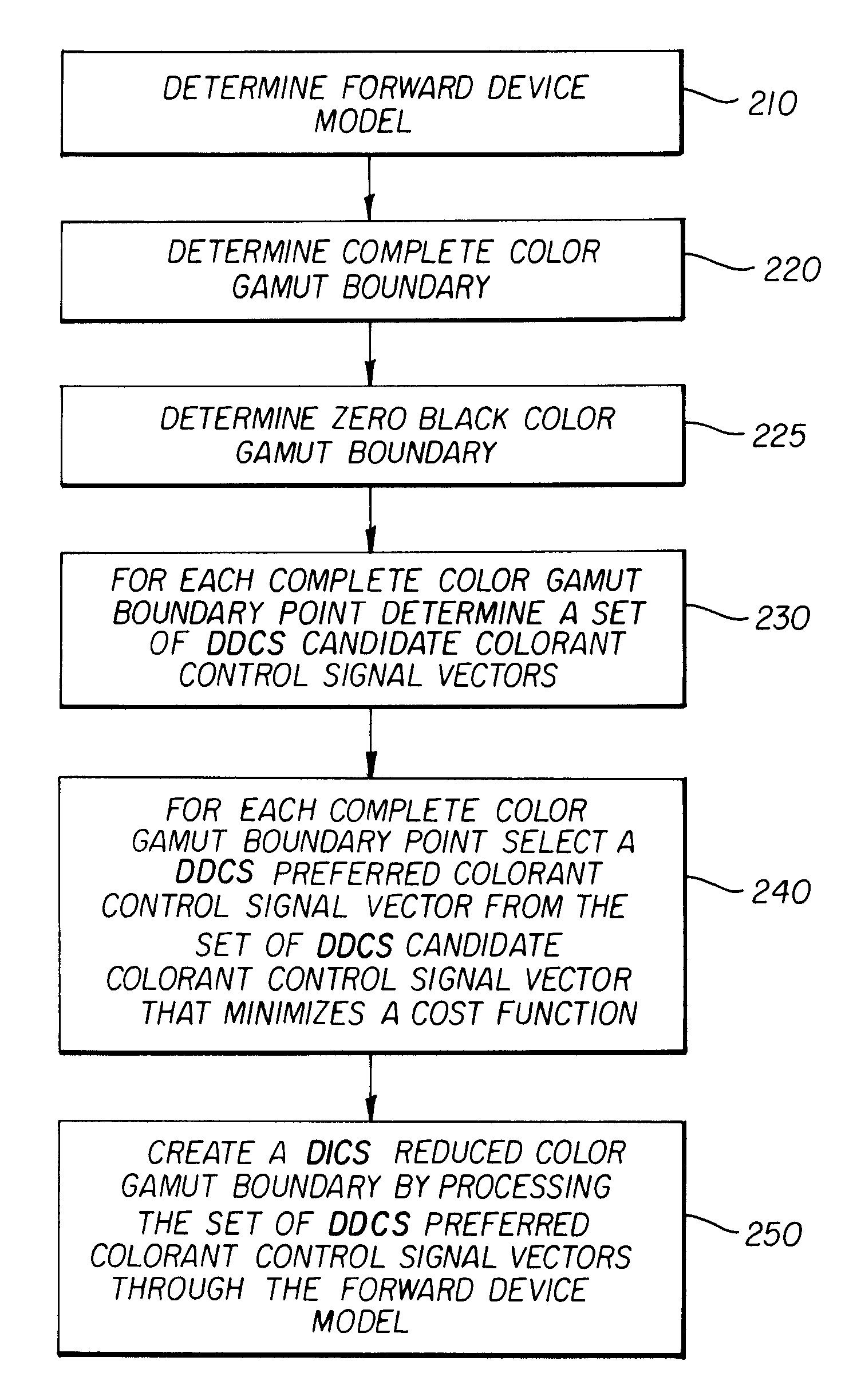
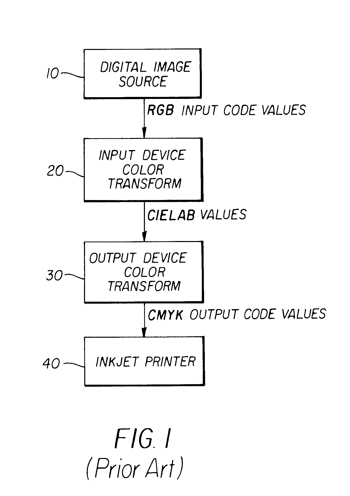
[0033]A method of generating a reduced color gamut and / or a color gamut mapping transform that provides for accurate total colorant amount limiting, pleasing color reproduction, and control over graininess represents an advancement in the state of the art. A preferred embodiment of the present invention achieving these goals will be described herein below. The invention will be described in the context of a color output device consisting of an inkjet printer using CMYK inks, but one skilled in the art will recognize that the scope of the invention is not limited to this arrangement, and may be applied to other colorant sets and / or other printing or display technologies as well.

[0034]Referring to FIG. 3, a process is detailed that produces a reduced color gamut boundary (gamut surface descriptor) for a CMYK color printing system that includes the step of first determining a forward device model for the color imaging device 210. There are many ways in which the forward device model ma...


PUM

PropertyMeasurementUnit
degree of freedomaaaaaaaaaa
volumeaaaaaaaaaa
colorsaaaaaaaaaa

Abstract

A method of generating a reduced color gamut boundary for a color output device using three or more colorants, wherein the amount of each colorant is controlled by a colorant control signal vector, including determining a forward device model for the color output device relating the colorant control signal vector to the corresponding output color; determining a complete color gamut boundary for the color output device, comprising a set of color gamut boundary points; and determining a set of candidate colorant control signal vectors for each point in the complete color gamut boundary. The method also includes selecting a preferred colorant control signal vector.

Description

CROSS REFERENCE TO RELATED APPLICATIONS[0001]Reference is made to commonly assigned U.S. patent application Ser. No. 09 / 881,460 filed Jun. 14, 2001 by Douglas Couwenhoven et al., entitled “Method for Multilevel Printing of Digital Images Using Reduced Colorant Amounts”, and commonly assigned U.S. patent application Ser. No. 10 / 309,866 filed concurrently herewith by Douglas W. Couwenhoven et al., entitled “Calibrating a Digital Printer Using a Cost Function”, the disclosures of which are herein incorporated by reference.FIELD OF THE INVENTION[0002]This invention pertains to digital imaging, and more particularly to a color transformation used in preparing a digital image for printing.BACKGROUND OF THE INVENTION[0003]For the purposes of the current invention, the term CIELAB refers to the prior art device independent color space (DICS) defined by the Commission Internationale De L'Eclairage (CIE). Those skilled in the art will recognize that the CIELAB color space is widely used in th...

Claims


Application Information

Patent Timeline
Patent Type & Authority Patents(United States)
IPC IPC(8): G06F15/00G03F3/08G06K9/00B41J2/525G06T1/00H04N1/46H04N1/60
CPCH04N1/6022H04N1/6058
Inventor BRAUN, GUSTAVCOUWENHOVEN, DOUGLAS W.SPAULDING, KEVIN E.WOOLFE, GEOFFREY J.
Owner EASTMAN KODAK CO
Why Eureka
Try Eureka