Optical recording medium, method of manufacturing optical recording medium, apparatus for manufacturing optical recording medium, program, and medium

a manufacturing method and optical recording technology, applied in the field of optical recording medium, can solve the problems of deteriorating not being able to be created using injection molding, not being able to be rewritten with ordinary optical disk recording/reproduction, etc., and achieve the effect of improving the accuracy of reading unique information

Active Publication Date: 2007-07-03
PANASONIC CORP
View PDF22 Cites 28 Cited by
  • Summary
  • Abstract
  • Description
  • Claims
  • Application Information

AI Technical Summary

Benefits of technology

[0015]Considering the problems above with the conventional techniques, the present invention aims at providing an optical recording medium, a method of manufacturing optical recording medium, an apparatus of manufacturing optical recording medium, a program, and a medium, with which it is possible to improve an accuracy of reading unique information which identifies an individual from an optical disk which comprises a plurality of information layers.
[0016]In light of the problems above with the conventional techniques, the present invention also aims at providing an optical recording medium, a method of manufacturing optical recording medium, an apparatus of manufacturing optical recording medium, a program, and a medium, with which it is possible to reduce a dedicated area which is for recording unique information which identifies an individual.

Problems solved by technology

Such identification information is different between individual mediums, and hence, can not be created using an injection molding method mentioned above.
In addition, it must be ensured that the information can not be rewritten with ordinary optical disk recording / reproducing apparatuses which are generally available in the market.
This may result in a deteriorated accuracy of reading the unique information which identifies an individual, or even in a complete failure of data read in the worst situation.
(In the case of a rewritable optical disk, in some cases, optimization of recording in each information layer becomes difficult, which in turn obstructs perfect crystallization or exerts an influence such as deformation induced by excessive heat.)
In addition, since the area dedicated to BCA recording which is large but has a small capacity gets occupied when the conventional BCA recording method is used, a read-write area which is originally intended for writing of data may shrink and a substantial recording capacity may accordingly decrease.

Method used


Image

  • Optical recording medium, method of manufacturing optical recording medium, apparatus for manufacturing optical recording medium, program, and medium
  • Optical recording medium, method of manufacturing optical recording medium, apparatus for manufacturing optical recording medium, program, and medium
  • Optical recording medium, method of manufacturing optical recording medium, apparatus for manufacturing optical recording medium, program, and medium

Examples


first preferred embodiment

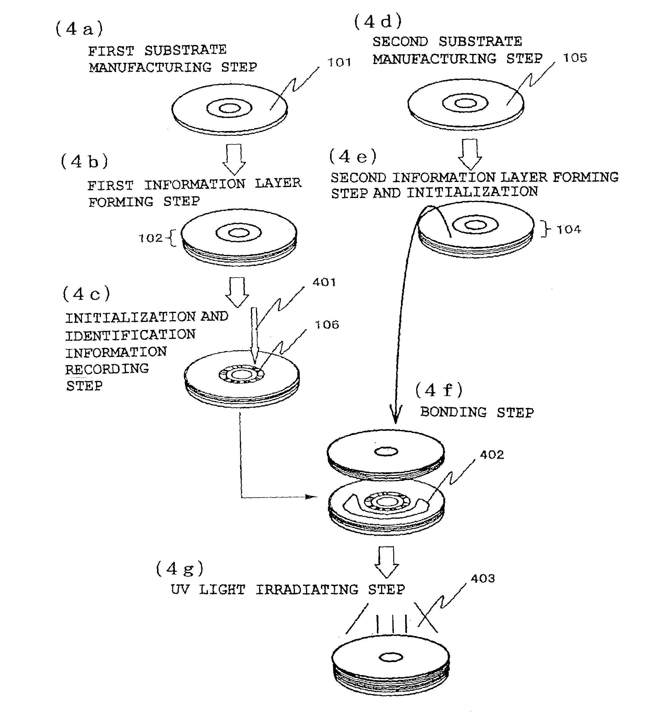
[0113]FIG. 4 is a drawing which shows steps of manufacturing an optical disk according to the first preferred embodiment which comprises the first information layer 102 and the second information layer 104 for holding information so that by means of incident light, (1) the information will be reproduced or (2) the information will be recorded and reproduced, and comprises the BCA area disposed in the first information layer 102 in which the individual identification information 106 uniquely given to the optical disk is recorded.

[0114]First, methods of manufacturing the first substrate 101 and the second substrate 105 will be illustrated. A detailed description will be provided later on recording of the information 106 (unique identification information) identifying an individual in an optical recording medium manufacturing apparatus (FIG. 6) which comprises a laser 401, which is a characteristic according to the first preferred embodiment.

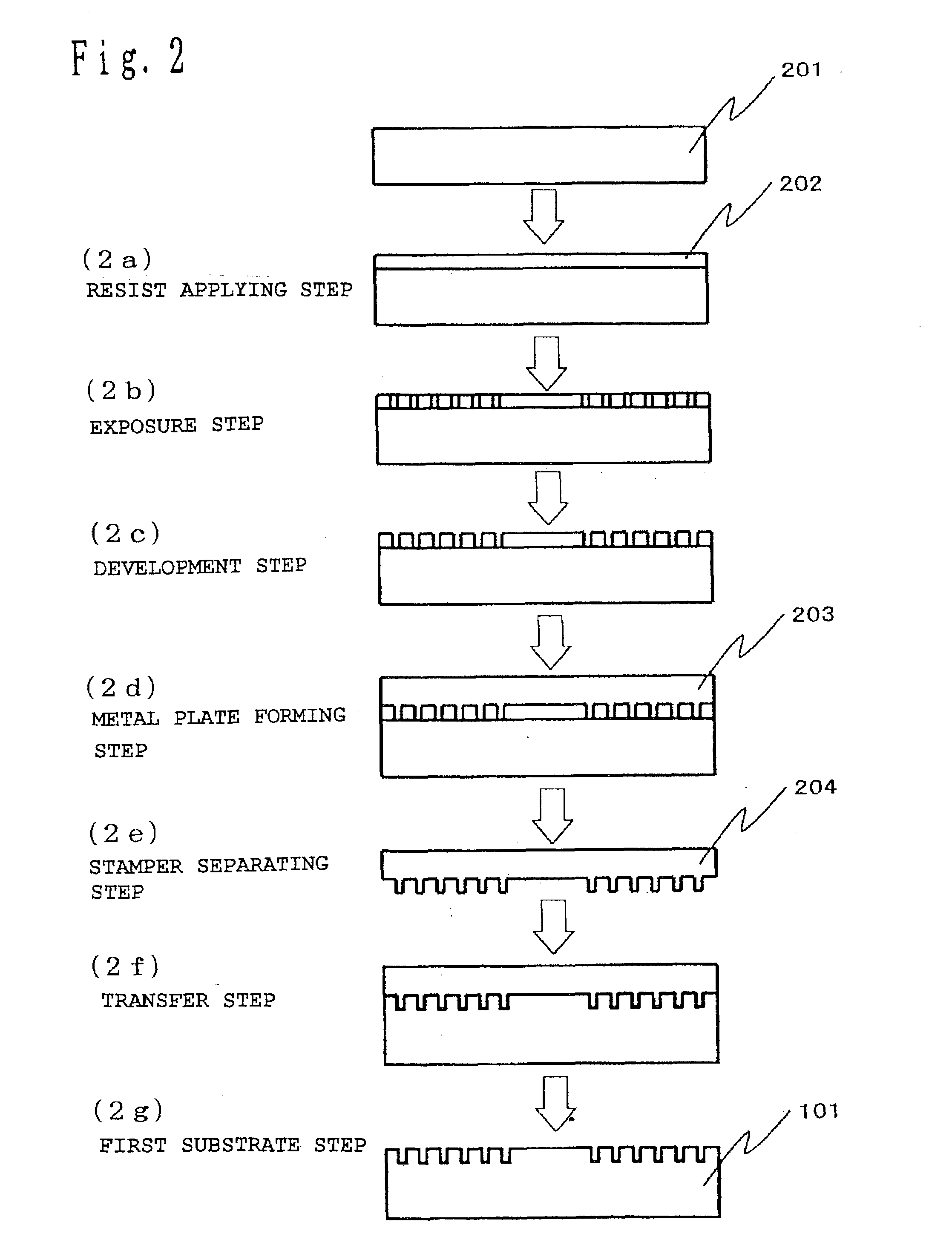
[0115]FIG. 2 is a drawing which shows a meth...

second preferred embodiment

[0132]FIG. 7 is a drawing which shows steps of manufacturing an optical disk according to the second preferred embodiment. The first substrate 101 is comprised of a synthetic resin such as polycarbonate, glass or metal, and formed by an injection molding method, the 2P method or the like using a stamper which is manufactured in a similar manner to that used in the first preferred embodiment (Step (7a)). The first information layer 102 is comprised of a reflection film formed by a metal thin film of aluminum or the like and a phase-change recording film which is rewritable and held between dielectric films, and is formed by sputtering or otherwise disposing the metal thin film, the dielectric film, the phase-change recording film and the dielectric film in this order (Step (7b)).

[0133]After forming the first information layer 102, the information 106 which identifies an individual is recorded (Step (7c)). A method of recording is similar to that used in the first preferred embodiment...

third preferred embodiment

[0141]FIGS. 9(a) and 9(b) are drawings of an optical disk according to the third preferred embodiment which comprises an information layer for holding information so that by means of incident light, (1) information will be reproduced or (2) information will be recorded and reproduced, wherein there is a predetermined position information recording area in which information regarding a position at which the individual identification information 905, which is given uniquely to the optical disk is recorded, is recorded.

[0142]The position information recording area according to the present invention corresponds to a BCA area 901 in the optical disk shown in FIG. 9(a) but to a lead-in area 902 in the optical disk shown in FIG. 9(b).

[0143]The optical disk shown in FIG. 9(a) is divided into the BCA area 901, the lead-in area 902, a learning area 903 and a data area 904, but into the lead-in area 902, the learning area 903 and the data area 904 in the optical disk shown in FIG. 9(b). Althou...


PUM

PropertyMeasurementUnit
thicknessaaaaaaaaaa
thicknessaaaaaaaaaa
thicknessaaaaaaaaaa

Abstract

There are some cases that an accuracy is low for reading unique information identifying an individual from an optical disk which comprises a plurality of information layers.The optical disk according to the present invention is an optical disk which comprises a first information layer and a second information layer for holding information so that, by incident light, (1) the information will be reproduced or (2) the information will be recorded and reproduced. The optical disk comprises a BCA area which is formed in the first information layer and in which individual identification information uniquely given to the optical disk is recorded.

Description

[0001]This Application is a U.S. National Phase Application of PCT International Application PCT / JP01 / 09650.FIELD OF THE INVENTION[0002]The present invention relates to an optical recording medium, a method of manufacturing optical recording medium, an apparatus of manufacturing optical recording medium, a program, and a medium.BACKGROUND OF THE INVENTION[0003]Over the recent years, as the volume of information required by audio / video equipment has increased, an increased attention has been paid to disk-shaped optical recording mediums, or so-called optical disks, which allow an easy access to data, storage of a large volume of data and superiority in reduction of the sizes of equipment. Optical disks include reproduction-only optical disks, write-once-read-many optical disks, phase-change type optical disks and magnetic optical disks as read-write optical disks, etc., which are called CDs, DVDs, MOs and the like and used in a variety of actual applications. An information layer in ...

Claims


Application Information

Patent Timeline
Patent Type & Authority Patents(United States)
IPC IPC(8): G11B7/24G11B7/007G11B7/24038G11B7/26G11B20/00
CPCG11B7/00736G11B20/00086G11B20/00094G11B7/26G11B7/24038Y10T428/21G11B7/268G11B7/24047G11B2220/235G11B2220/80
Inventor SATO, SHUJINISHIUCHI, KENICHI
Owner PANASONIC CORP
Why Eureka
Try Eureka