
Thermostat fan and boiler timer

a technology of thermostat fan and timer, which is applied in the direction of process and machine control, lighting and heating apparatus, instruments, etc., can solve the problems of pipes associated with the heating system freezing and burping, affecting the comfort of homeowners, and affecting the comfort of mobile home owners

Inactive Publication Date: 2007-07-10
WALSH JR JOHN MAURICE
View PDF11 Cites 28 Cited by
  • Summary
  • Abstract
  • Description
  • Claims
  • Application Information

AI Technical Summary

Benefits of technology

"The present invention is a thermostat fan and boiler timer that connects directly to an existing thermostat without the need for rewiring. It includes a microprocessor, AC / DC converter, zero crossing detector, switching means, and user interface. The timer can program the duration and interval of fan or boiler cycles, as well as the variable timing. The user interface can be any form that fits the function, including an LCD display and keypad or two LEDs and a switch. The switching means can be any device that serves the requisite function, in the preferred embodiment, it is a triac. The invention also includes a method of circulating heated air throughout a building or structure and a method of circulating hot water throughout a heating system using the thermostat fan and boiler timer of the present invention."

Problems solved by technology

This temperature differential can be uncomfortable to the homeowner.
This circumstance can cause pipes associated with the heating system to freeze and burst because the water in them is never circulated.
Mobile home owners experience similar problems.
In that event, the water pipes can freeze and burst because they are not receiving warm air from the furnace.
It also draws power continuously from the gas solenoid through a 680 ohm resistor, and this method has proven to be problematic in practice.
In addition, this invention, like the Flanders invention, has to be inserted into the existing circuit and thus can cause problems with the heating and cooling system if it fails.
It requires a power source and, therefore, cannot mount directly to the thermostat.

Method used


Image

  • Thermostat fan and boiler timer
  • Thermostat fan and boiler timer
  • Thermostat fan and boiler timer

Examples


Embodiment Construction

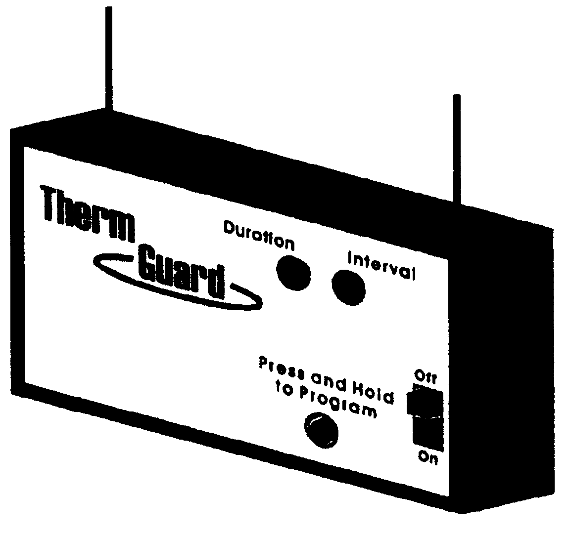
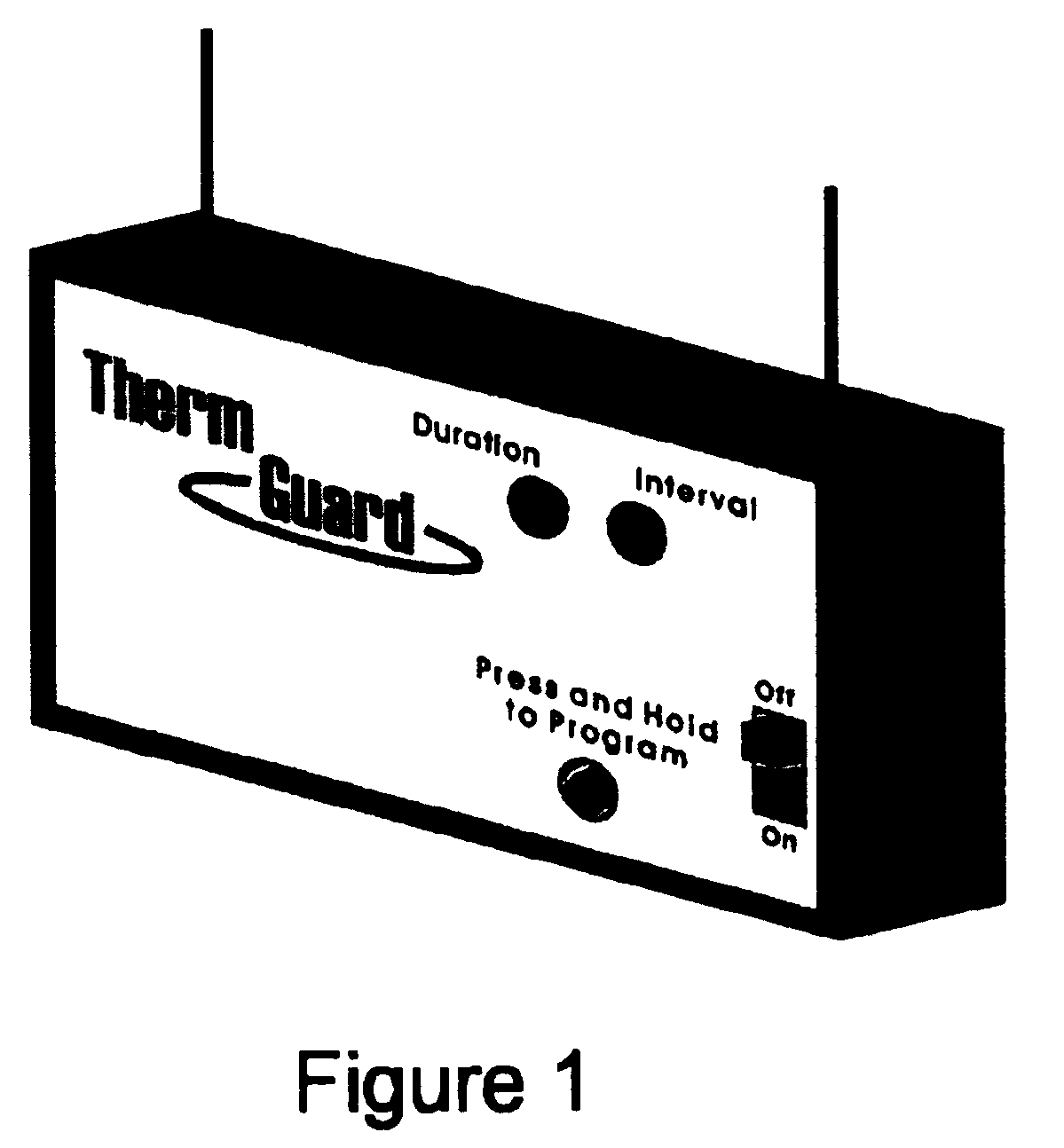
[0049]FIG. 1 is a pictorial illustration of the preferred embodiment of the invention. The present invention connects directly to an existing thermostat through the use of only two wires and without the need for rewiring any of the thermostat connections. It can be mounted on the wall near the thermostat or located anywhere else in the house, as long as it can be connected to the thermostat wires.

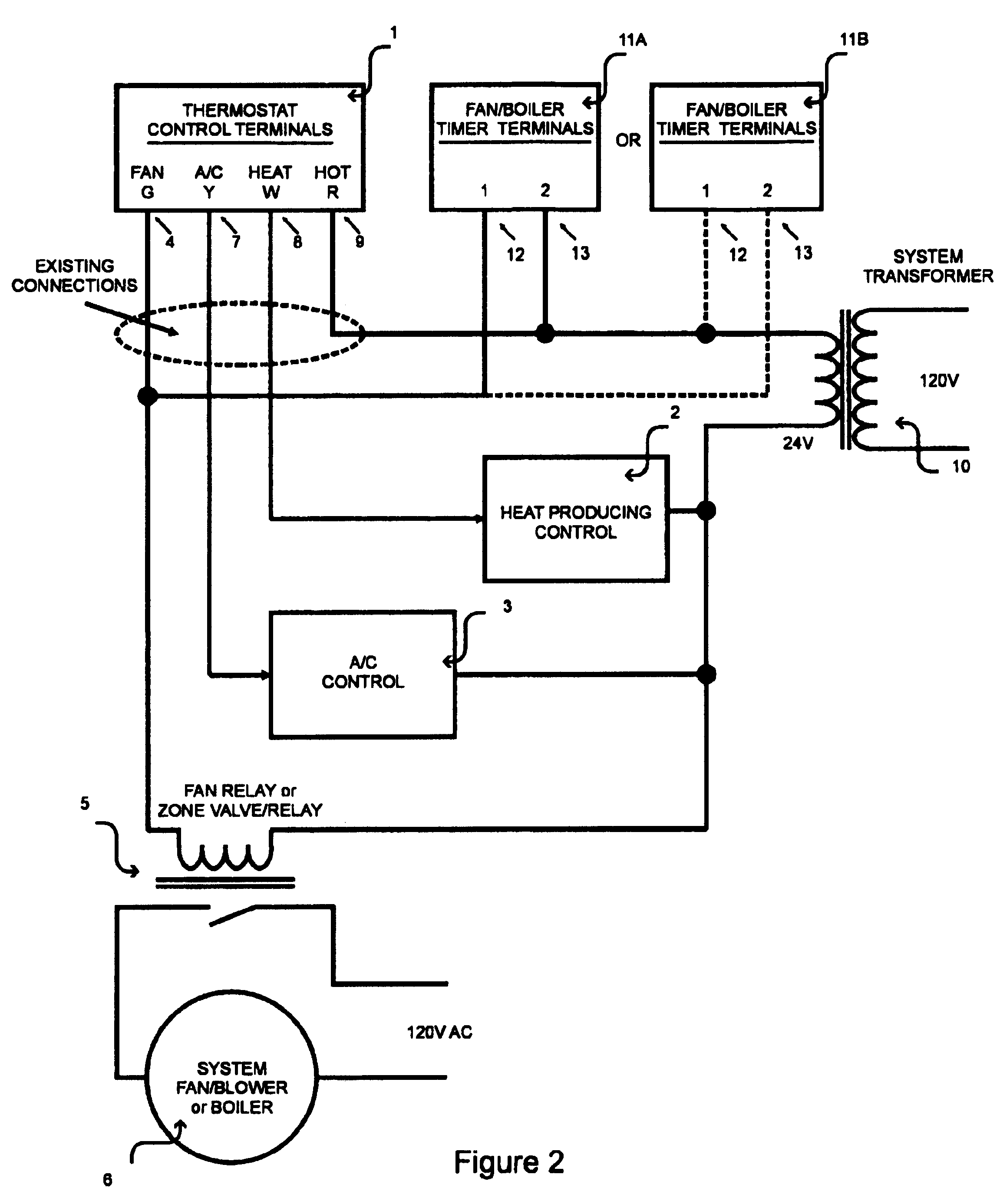
[0050]FIG. 2 illustrates, in block diagram form, the configuration of the present invention in relation to an existing household thermostat 1. This unit is typically connected as shown when the home has a furnace 2 and air conditioning unit 3. The fan contact terminal 4 connects the thermostat 1 to the fan / blower relay 5. When actuated, the fan relay 5 connects the system fan / blower 6 to the 120 VAC. The air conditioning contact terminal 7 connects the thermostat 4 to the air conditioning control circuitry 3. The heater contact terminal 8 connects the thermostat to the heat producing contro...


PUM


Abstract

A programmable timer circuit that can be connected directly to the fan switch of any thermostat with a forced air heating and / or cooling system that includes a blower fan for circulating air throughout the home. A programmable timer circuit that can be connected directly to any thermostat used in a hot-water heated home with a boiler and pump for circulating hot water through the heating system. The timer can be installed with no modifications to the existing wiring and has interchangeable leads to make installation quick and easy. The present invention increases the efficiency of the heating / cooling system, and in homes with auxiliary heat sources, circulates the warm air throughout the home to increase comfort levels. The present invention is programmable with a single button. A method of circulating hot air and / or hot water throughout a home using the timer device of the present invention.

Description

CROSS-REFERENCE TO RELATED APPLICATION[0001]This application is an original provisional application. It does not claim priority back to any previously filed patent application.BACKGROUND OF THE INVENTION[0002]1. Field of the Invention[0003]The present invention relates to a programmable timer circuit that can be connected directly to the fan switch of any thermostat with a forced air heating and / or cooling system that includes a blower fan for circulating air throughout the home. The present invention also relates to a programmable timer circuit that can be connected directly to any thermostat used in a hot-water heated home with a boiler and pump for circulating hot water through the heating system.[0004]2. Description of the Related Art[0005]In homes that use an auxiliary heat source such as a wood, gas or pellet stove or a fireplace, the air in the room in which the heat source is located can become quite warm while the temperature in the rest of the home is exceedingly cool. Thi...

Claims


Application Information

Patent Timeline
Patent Type & Authority Patents(United States)
IPC IPC(8): G05D23/19F23N5/20
CPCF23N5/203
Inventor WALSH, JR., JOHN MAURICE
Owner WALSH JR JOHN MAURICE
Learn More