System for measuring FET characteristics

a technology of characteristics and measurement systems, applied in the field of system for measuring characteristics of fets, can solve the problems of insufficient stability of output voltage for pulse widths of 100 ns or less, and the dc voltage applied to the gate of fets cannot provide reliable measurement, so as to achieve the effect of enhancing the measurement accuracy of fet characteristics

Active Publication Date: 2007-07-10
KEYSIGHT TECH
View PDF4 Cites 9 Cited by
  • Summary
  • Abstract
  • Description
  • Claims
  • Application Information

AI Technical Summary

Benefits of technology

[0008]Accordingly, an object of the present invention is to provide an FET-characteristic measuring system that is capable of more accurately measuring the IV characteristics of advanced FETs, such as SOI MOSFETs, strained-silicon MOSFETs, or MOSFETs using high-k (high dielectric constant) gate insulators.
[0014]According to the present invention, the voltage of the pulse output from the pulse generator is measured via the divider, and based on the result of the measurement, the voltage of the pulse output from the pulse generator is adjusted so that a gate voltage having a predetermined value is applied to the gate of the FET. Thus, even when the voltage output from the pulse generator does not match the set voltage, the measurement accuracy of the FET characteristic can be enhanced by applying a gate voltage having a desired value to the gate of the FET.

Problems solved by technology

However, for measuring the IV characteristic of an advanced MOSFET, such as a SOI (silicon on insulator) MOSFET, a strained-silicon MOSFET, or a MOSFET using a high-k (high dielectric constant) gate insulator, the known measuring method in which a DC voltage is applied to the gate of the FET cannot provide a reliable measurement result of the IV characteristic because of a self-heating phenomenon exhibited by the FET.
However, since the value of a voltage output from the pulse generator is generally guaranteed only for a sufficiently long pulse width, the output voltage is in many cases not sufficiently stable for a pulse width of 100 ns or less.
Thus, with a pulse having a pulse width of 100 ns or less, it is not desirable to directly use the output of the pulse generator from the viewpoint of providing high measurement accuracy.

Method used


Image

  • System for measuring FET characteristics
  • System for measuring FET characteristics
  • System for measuring FET characteristics

Examples


Embodiment Construction

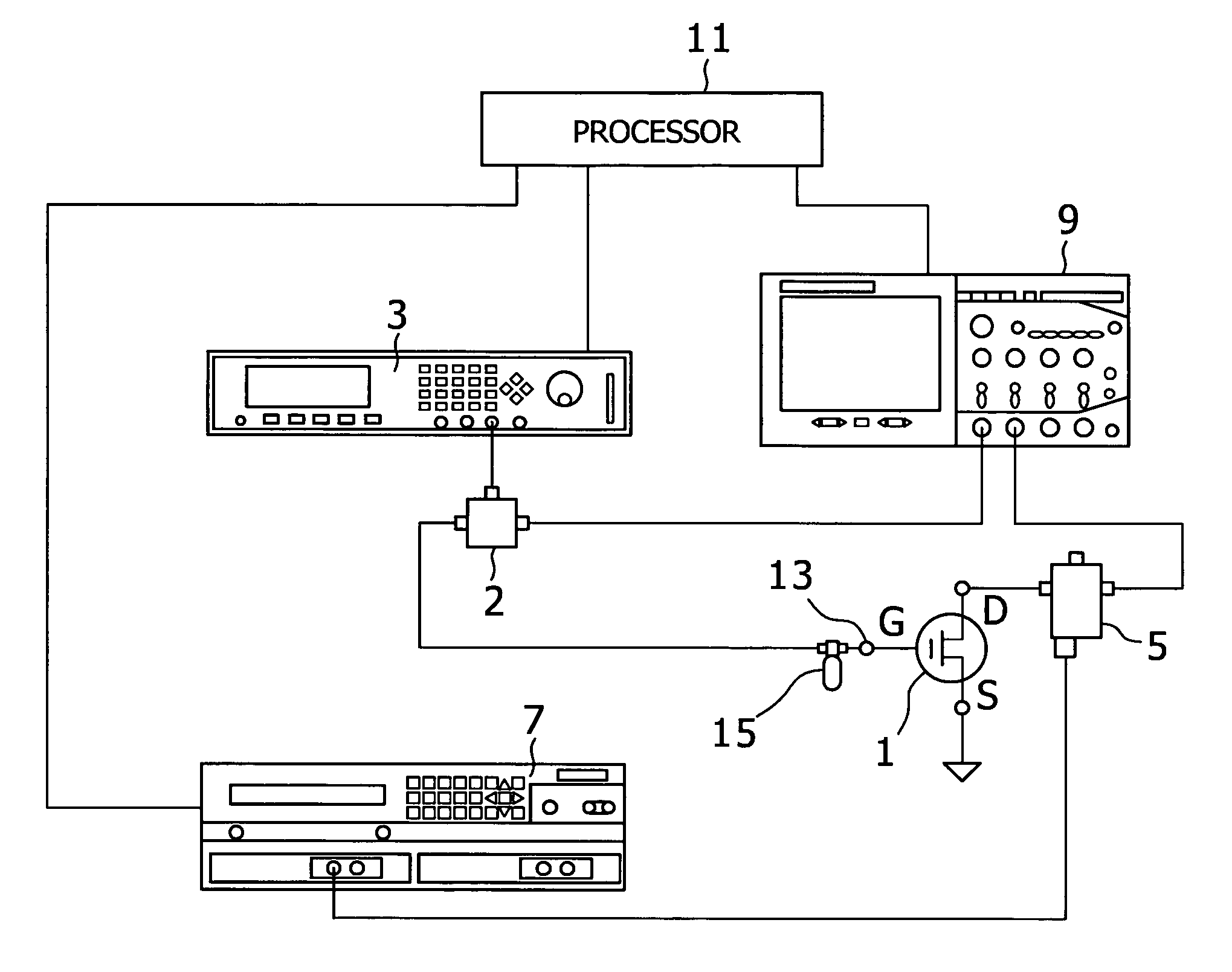
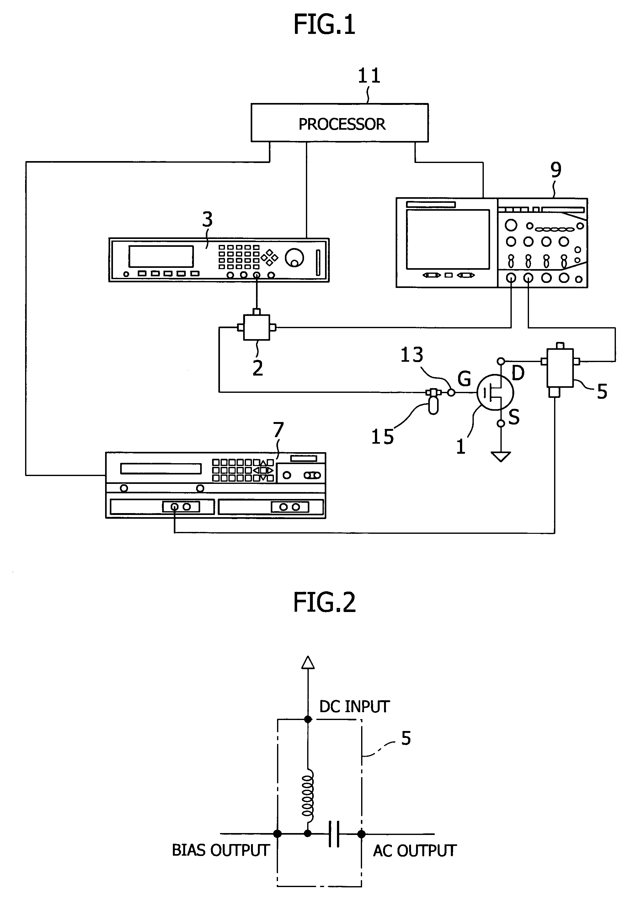
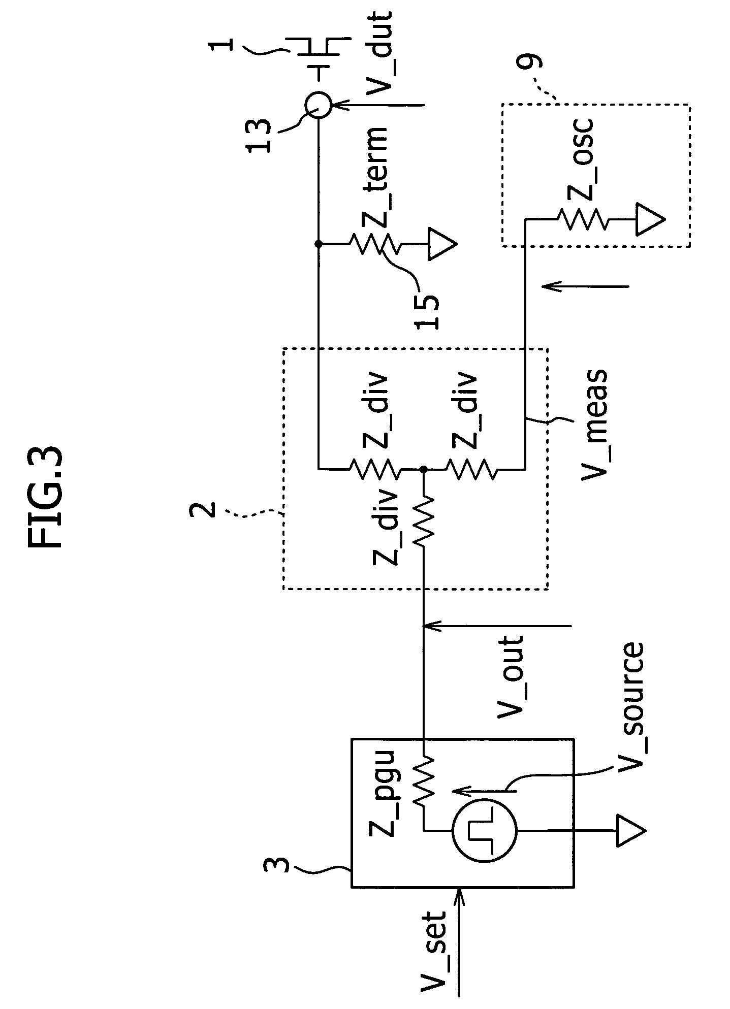
[0018]FIG. 1 is a block diagram illustrating the configuration of an FET-characteristic measuring system according to the present invention. This FET-characteristic measuring system applies a short-duration pulse (e.g., 100 ns or less) to an FET 1 to measure the IV (current-voltage) characteristic thereof

[0019]The FET 1 shown in FIG. 1 is a MOSFET manufactured by SOI (silicon on insulator) technology or strained-silicon fabrication technology.

[0020]The gate of the FET 1 is connected to the pulse generator 3 via a divider 2, and the drain of the FET 1 is connected to a current / voltage source 7 and a terminal (channel 2 in the example shown in FIG. 1) of an oscilloscope 9 (which may be a digital oscilloscope) via a so-called bias tee 5.

[0021]The DC voltage source 7 may be implemented with, for example, an SMU (source measure unit) capable of applying a high-accuracy DC voltage and measuring a current.

[0022]An example of the SMU is Agilent 4156 manufactured by Agilent Technologies, Inc...


PUM

PropertyMeasurementUnit
matching impedanceaaaaaaaaaa
external impedanceaaaaaaaaaa
voltageaaaaaaaaaa

Abstract

An FET-characteristic measuring system applies a pulse output from a pulse generator to the gate of an FET in order to measure drain current flowing through the FET. The pulse has a voltage based on a set voltage. The measuring system includes a divider for dividing the pulse output from the pulse generator into a first pulse applied to the gate of the FET and a second pulse for voltage measurement; a voltage measuring device for measuring a voltage of the second pulse; and a set-voltage adjusting device for determining, based on the voltage of the second pulse, a target set voltage for the pulse generator to apply a pulse having a desired gate application voltage to the FET and for adjusting the set voltage to the target set voltage so that a voltage of the first pulse is equal to the desired gate application voltage.

Description

BACKGROUND OF THE INVENTION AND RELATED ART STATEMENT[0001]1. Field of the Invention[0002]The present invention relates to a system for measuring characteristics of an FET (field effect transistor) in which a gate voltage in the form of a pulse having a set output voltage from a pulse generator is applied to the gate of an FET in order to measure drain current flowing through the FET. More specifically, the present invention relates to adjustment of the set voltage of the pulse generator so that a desired voltage is accurately applied to the gate of the FET.[0003]2. Description of the Related Art[0004]The IV (current-voltage) characteristics of an FET are determined by applying a predetermined DC (direct current) voltage to the gate of the FET while a predetermined bias voltage is applied to the drain.[0005]However, for measuring the IV characteristic of an advanced MOSFET, such as a SOI (silicon on insulator) MOSFET, a strained-silicon MOSFET, or a MOSFET using a high-k (high diele...

Claims


Application Information

Patent Timeline
Patent Type & Authority Patents(United States)
IPC IPC(8): G01R27/08G01R31/26
CPCG01R31/2621G01R19/165G01R31/26H01L22/00
Inventor OKAWA, YASUSHI
Owner KEYSIGHT TECH
Why Eureka
Try Eureka