
Directed sequential hazard assessment weather radar

a weather radar and hazard assessment technology, applied in the field of weather radar, can solve the problems of incompatibility with the rapid update requirements, time-consuming volume scans, and inability to detect or assess hazards, and the radar may not be optimized for either detection or assessmen

Active Publication Date: 2007-07-10
ROCKWELL COLLINS INC
View PDF18 Cites 131 Cited by
  • Summary
  • Abstract
  • Description
  • Claims
  • Application Information

AI Technical Summary

Benefits of technology

[0023]It is an advantage of the present invention to use an optimized reflectivity process in detection mode and a situationally optimized radar sample / antenna in the assessment mode to detect a weather hazard.
[0024]It is an advantage of the present invention to use an optimized reflectivity process in detection mode and an optimized vertical hail inference process in the assessment mode when needed.
[0025]It is an advantage of the present invention to provide a qualification mode to determine if a hazard is real.
[0026]It is a feature of the present invention to be able to inset new threat detection and assessment modes as they are needed.
[0027]It is feature of the present invention to be able to detect turbulence and storm tops.

Problems solved by technology

A detectable hazard may be present when the aircraft flight path intersects an area in and around a thunderstorm.
Such volume scans are time consuming and are not compatible with the rapid update requirements needed in a dynamic aircraft environment.
This time consuming volume scan generally forces the radar to support both detection and assessment of a hazard with the same sampled data.
Therefore the radar may not be optimized for either detection or assessment but supports a compromised data set that provides suboptimal detection and suboptimal assessment.

Method used


Image

  • Directed sequential hazard assessment weather radar
  • Directed sequential hazard assessment weather radar
  • Directed sequential hazard assessment weather radar

Examples


Embodiment Construction

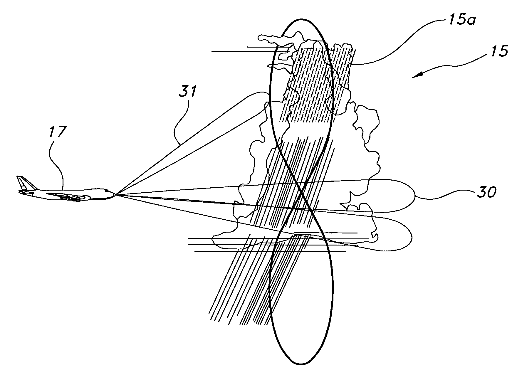
[0035]The present invention is for a directed sequential hazard assessment weather radar system for detecting weather and hazards with low latency and high confidence. In the directed sequential hazard assessment weather radar system, initial detection of a hazard is separated from assessment of the hazard. The present invention may be used for supporting turbulence detection, storm top detection, hail detection, lighting threat assessment, and all other hazards that are detectable or can have their existence inferred by a weather radar system.

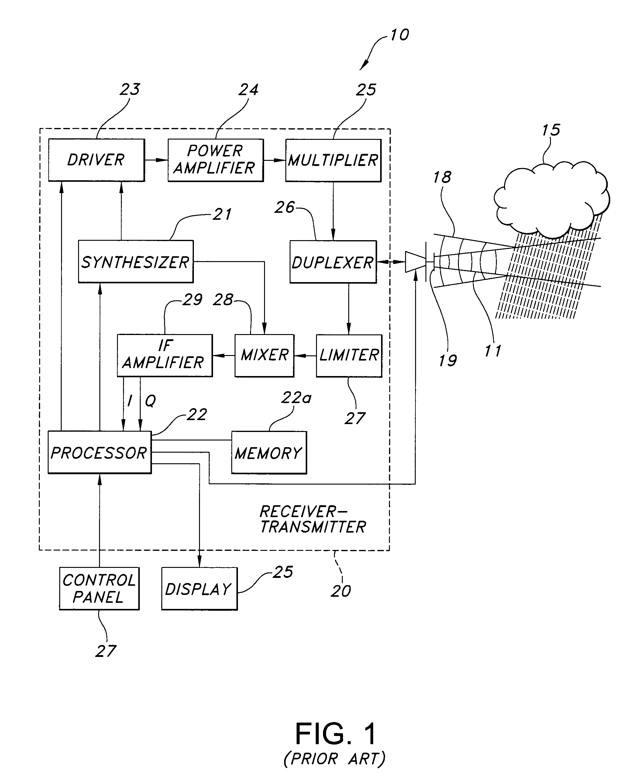
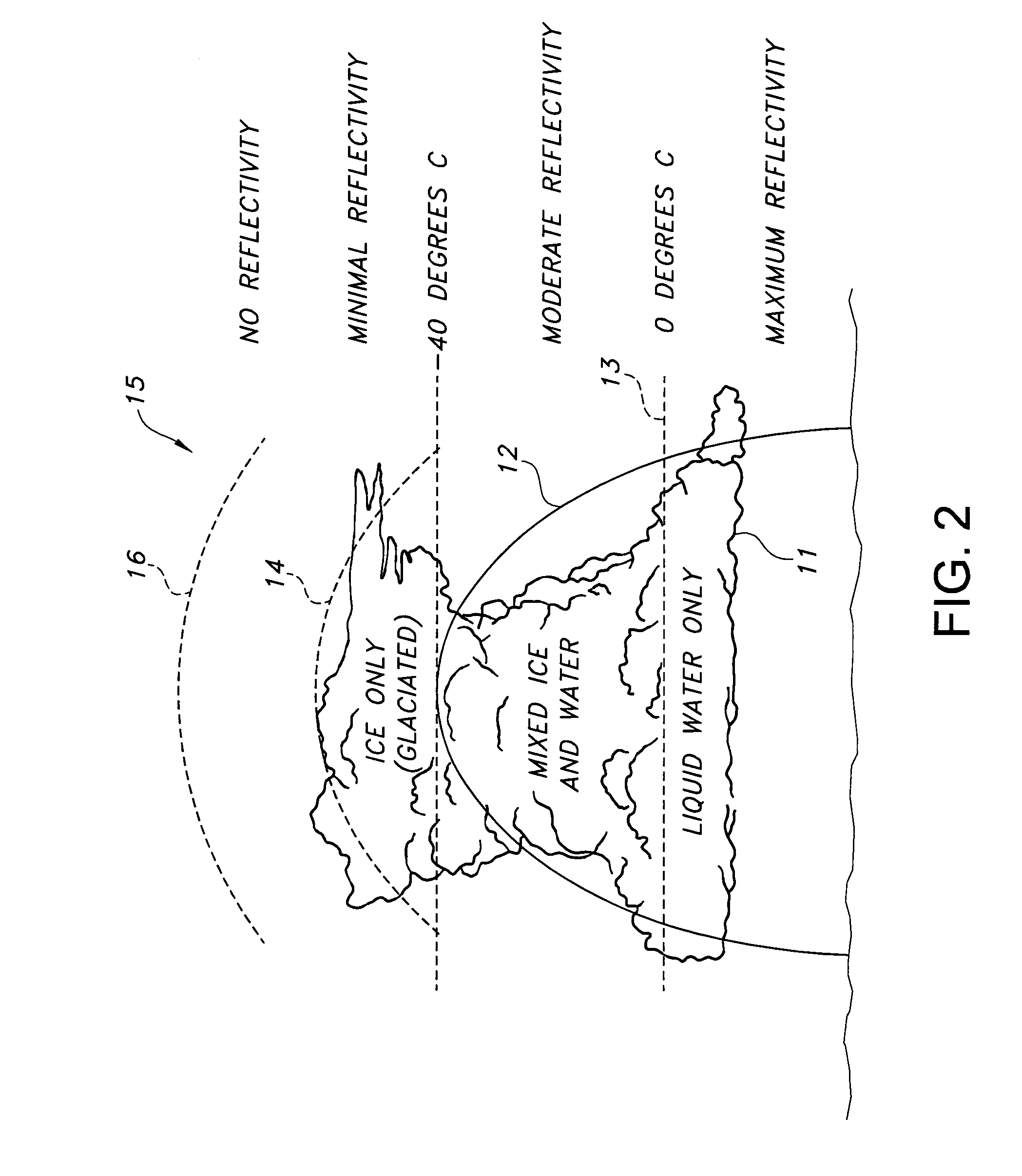
[0036]Weather radars are known in the art for detecting severe weather and for providing a flight crew in an aircraft a two-dimensional map display showing range, bearing, and intensity of detected weather patterns. Flight hazards due to weather conditions are primarily the result of precipitation and turbulence. A block diagram of a representative weather radar 10 that may incorporate the present invention for directed sequential hazard asses...


PUM


Abstract

A directed sequential hazard assessment weather radar system detects weather and hazards with low latency and high confidence in a hazard detection mode to detect a region of reflectivity and changes to an assessment mode after detecting the region of reflectivity. The weather radar system scans a volume in front of an aircraft to detect the region of reflectivity in the hazard detection mode using a multiscan process and a reflectivity pulse pattern. The weather radar system determines presence of a hazard in the region of reflectivity after detecting the region. The weather radar system changes to a turbulence pulse pattern in the assessment mode and scans the region of reflectivity with an auxiliary sweep to determine turbulence. The directed sequential hazard assessment weather radar system performs a qualification process by scheduling an additional radar scanning auxiliary sweep to determine if the turbulence is real.

Description

BACKGROUND OF THE INVENTION[0001]This invention relates to weather radar and specifically for a weather radar capable of rapid detection and alerting of weather hazards.[0002]Aviation weather hazards include the following: turbulence, hail, lightning, very high precipitation rates, low level windshear, and icing. Some of these hazards may be directly detected while others may be inferred by detecting the type of weather features they are associated with. Turbulence, hail, lightning, and very high rain rates are only associated with convective weather cells. Therefore separating the detection problem into detection of convective weather verses non-convective weather can be very useful. Low-level windshear and icing may be produced by both convective weather as well as other weather types such as stratiform or orthographic weather.[0003]A detectable hazard may be present when the aircraft flight path intersects an area in and around a thunderstorm. Since the aircraft may be flying ove...

Claims


Application Information

Patent Timeline
Patent Type & Authority Patents(United States)
IPC IPC(8): G01S13/95
CPCG01S7/41G01S13/953Y02A90/10
Inventor WOODELL, DANIEL L.
Owner ROCKWELL COLLINS INC
Learn More