Discrete circuit for driving field effect transistors

a field effect transistor and discrete circuit technology, applied in the field of field effect transistors, can solve the problems of relatively expensive pre-fet driver ics, relatively expensive way to drive a single fet, and cost damage to the fet, so as to improve the space efficiency and layout of the printed circuit board, and reduce the cost of short circuit detection and shut off time. , the effect of less expensiv

Inactive Publication Date: 2007-07-10
RPX CORP
View PDF5 Cites 5 Cited by
  • Summary
  • Abstract
  • Description
  • Claims
  • Application Information

AI Technical Summary

Benefits of technology

[0012]An advantage of the present invention is that discrete driving circuits are less expensive than Pre-FET driver ICs.
[0013]Another advantage is that the short circuit detection and shut off time is faster with the discrete driving circuits than with Pre-FET driver ICs.
[0014]Yet another advantage is that the short circuit voltage threshold or short circuit current threshold of the FETs are individually controllable.
[0015]A further advantage is that the components of the discrete driving circuits can be mounted on either side of the printed circuit board to thereby improve the space efficiency and layout of the printed circuit board.

Problems solved by technology

If a load connected to the FET shorts out, or if a service technician inadvertently connects a wiring harness in a wrong orientation, it is possible that a FET may be directly,connected to battery voltage, which may result in costly damage to the FET.
A problem is that Pre-FET driver ICs are relatively costly.
Thus, even if only one FET needs to be driven, the minimum configuration of a four channel driving device must be used, which is a relatively costly way to drive a single FET.
Another problem with Pre-FET driver ICs is that each of the channels has a common short-to-battery detection voltage threshold.
Thus, it is difficult to interface one single pre-FET driver with a group of FETs that have very large differences in their internal resistances.
Yet another problem with Pre-FET driver ICs is that they require a fixed turn-off time to switch off their outputs in order to protect the FETs in the event of a short-to-battery.
During this time, the peak short circuit current can rise up to a maximum of 28 to 40 Amps, which can result in damage to the FETs.

Method used


Image

  • Discrete circuit for driving field effect transistors
  • Discrete circuit for driving field effect transistors
  • Discrete circuit for driving field effect transistors

Examples


Embodiment Construction

[0021]The embodiments discussed below are not intended to be exhaustive or limit the invention to the precise forms disclosed in the following detailed description. Rather, the embodiments are chosen and described so that others skilled in the art may utilize their teachings.

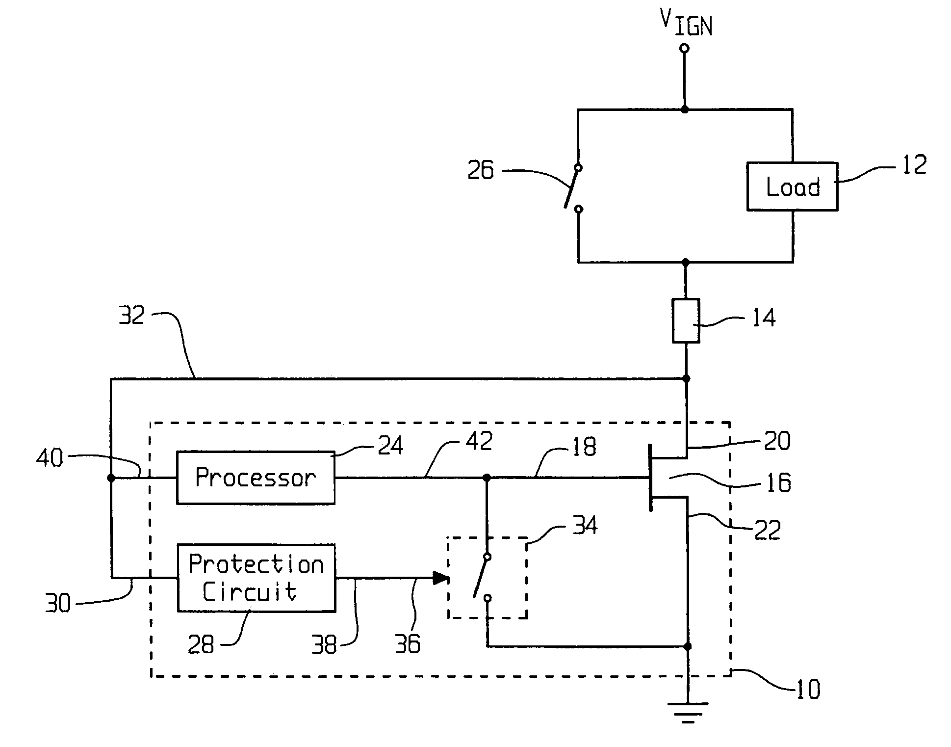
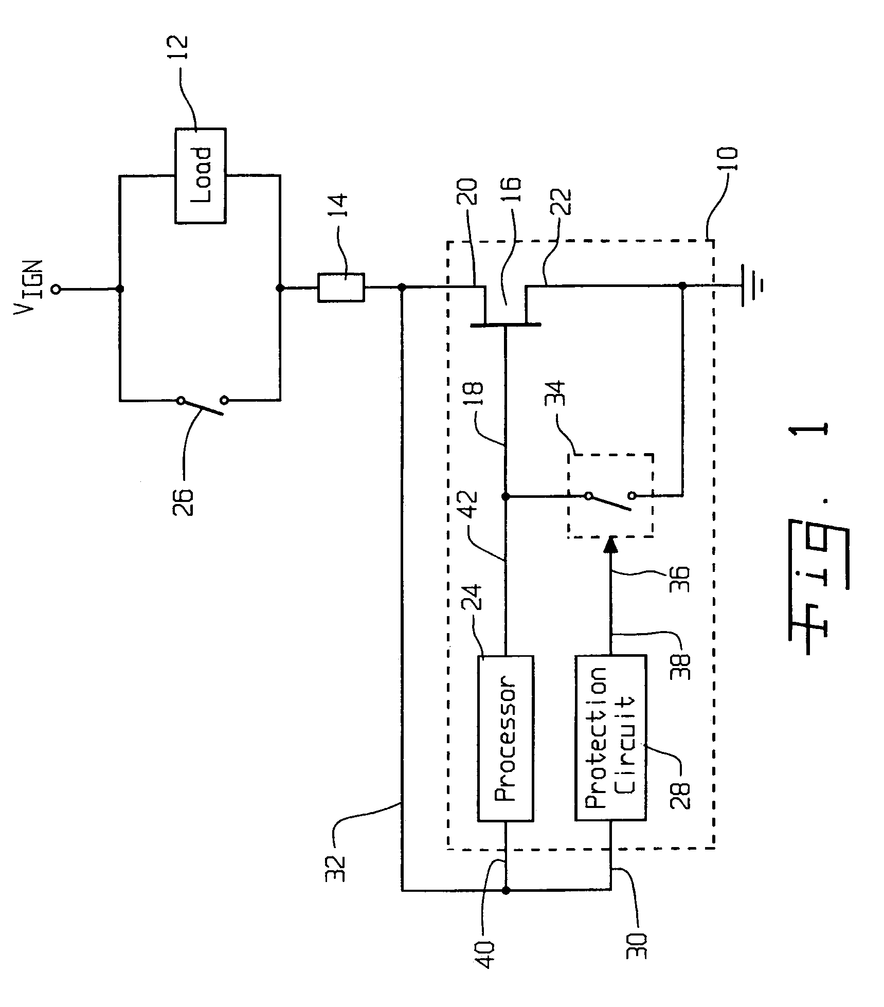
[0022]One embodiment of an electronic switching circuit 10 of the present invention for driving a load 12 is shown in FIG. 1. A wiring harness 14 may electrically interconnect circuit 10 and load 12. In an automotive application, a voltage source provides a vehicle ignition voltage VIGN that may be applied to load 12. Circuit 10 is connected to electrical ground such that circuit 10 may selectively provide a current path from VIGN to ground through load 12, wiring harness 14 and circuit 10. That is, circuit 10 may selectively provide either a short circuit from harness 14 to ground, thereby enabling current to flow through load 12, or an open circuit between harness 14 and ground, thereby preventing current from...


PUM


Abstract

An electronic circuit for protecting a field effect transistor from high voltage includes a switching device having a first state in which the switching device turns the field effect transistor ON, and a second state in which the switching device turns the field effect transistor OFF. A charging device is connected to the switching device and receives an electrical charge when an electrode of the field effect transistor is shorted to a voltage source. The charging device applies the electrical charge to the switching device to thereby place the switching device in the second state.

Description

BACKGROUND OF THE INVENTION[0001]1. Field of the Invention[0002]The present invention relates to field effect transistors and, more particularly, to circuits for driving field effect transistors.[0003]2. Description of the Related Art[0004]High power field effect transistors (FETs) may be driven by what is referred to as Pre-FET drivers in the form of integrated circuits (ICs). Such Pre-FET drivers may also function to protect the FETs in case of fault conditions such as short-to-battery and short-to-ground, etc. For example, FETs are often used in automotive electronic devices, such as engine control modules (ECMs). If a load connected to the FET shorts out, or if a service technician inadvertently connects a wiring harness in a wrong orientation, it is possible that a FET may be directly,connected to battery voltage, which may result in costly damage to the FET. Another possible function of the Pre-FET driver is to report the fault status back to the microprocessor for further pro...

Claims


Application Information

Patent Timeline
Patent Type & Authority Patents(United States)
IPC IPC(8): H02H9/00
CPCH03K17/0822
Inventor NAIR, BALAKRISHNAN VKILGOUR, GERALD A
Owner RPX CORP
Why Eureka
Try Eureka