Grating-outcoupled cavity resonator having uni-directional emission

a cavity resonator and grating technology, applied in the direction of optical resonator shape and construction, semiconductor laser structure details, semiconductor lasers, etc., can solve the problems of undesirable multi-directional emission, inappropriate multi-directional emission, etc., to achieve high output levels, large gain-length products, and the effect of tuning the efficiency of outcoupling over a wide rang

Inactive Publication Date: 2007-07-10
PALO ALTO RES CENT INC
View PDF10 Cites 30 Cited by
  • Summary
  • Abstract
  • Description
  • Claims
  • Application Information

AI Technical Summary

Benefits of technology

[0020]In various exemplary embodiments, the grating can extend over the entire circumference of the microdisk resonator to achieve maximum output power. In various exemplary embodiments, the grating is chirped, i.e., the grating period varies slightly over the region of the grating, to broaden the spectral width of the outcoupled light and increase its intensity. In some exemplary embodiments, the grating is formed in patterns that allow shaping of the outcoupled beam.
[0023]Because the light amplification in the grating-outcoupled microcavity disk resonators according to this invention occurs in the plane of the laser resonator, the gain×length product is very large. As a result, high output levels can be achieved. The outcoupling through a grating region, such as, for example, a second-order distributed feedback (DFB) grating implemented in the plane of the resonator, allows surface emission and all the advantages associated with such surface emission. Since the amplification process takes place in the plane of the resonator, while the outcoupling is accomplished by a grating region, the design and performance of the laser cavity is basically independent of the design of the output coupler, and outcoupling efficiency can be tuned over a wide range without affecting other laser parameters. For example, the grating outcoupled microdisk resonator would be less sensitive to temperature variation than a VCSEL. A distributed feedback grating, if used, is also much easier to fabricate than dielectric distributed Bragg reflector mirror stacks and is almost independent of the material system.

Problems solved by technology

Multi-directional emissions such as those produced by asymmetric resonant cavities are undesirable for a number of reasons, including low beam intensity, because the output modes are shared by the emitted beams.
For a variety of applications, multi-directional emission is inappropriate.

Method used


Image

  • Grating-outcoupled cavity resonator having uni-directional emission
  • Grating-outcoupled cavity resonator having uni-directional emission
  • Grating-outcoupled cavity resonator having uni-directional emission

Examples


Embodiment Construction

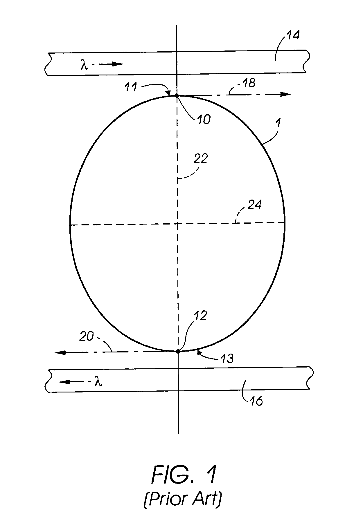
[0056]FIG. 1 shows a known embodiment of an asymmetric resonant cavity 1, wherein two axes of discrete symmetry 22 and 24 remain in the shape of the non-circular resonator 1. Because of the quadrupolar shape of the asymmetric resonant cavity 1, there is a point of maximum curvature 11 and 13 at each pole 10 and 12, respectively. Modes circulating in both the counterclockwise and clockwise directions in the asymmetric resonant cavity 1 are low loss, and therefore high gain. Because of the discrete symmetry of the asymmetric resonant cavity 1, the clockwise and counterclockwise modes are degenerate, and each mode will output one beam at each point of maximum curvature 11 and 13. Therefore, if this asymmetric resonant cavity 1 were to be electrically pumped, four output beams would be produced, one for each circulating mode, for each point of maximum curvature 11 and 13. Therefore, this non-circular resonator 1 is not uni-directional, in that at least four output beams are produced whe...


PUM


Abstract

A grating-outcoupled microcavity disk resonator has whispering gallery modes existing in a nearly circular resonator. Light is outcoupled by providing a grating region in the plane of the grating-outcoupled microcavity disk resonator. The grating region provides an outcoupling or loss mechanism that symmetrically interacts with the clockwise and counterclockwise whispering gallery modes, thereby making the resonator capable of surface emission.

Description

[0001]This invention was made with U.S. Government support awarded by the Defense Advance Research Projects Agency (DARPA). The U.S. Government has certain rights in this invention, including the right in limited circumstances to require the patent owner to license others on reasonable terms as provided for by the terms of Contract No. N66001-02-C-8017.BACKGROUND OF THE INVENTION[0002]1. Field of Invention[0003]This invention is directed to cavity resonators and optical devices involving cavity resonators as a component.[0004]2. Description of Related Art[0005]Cavity resonators are components in optical devices such as lasers, filters, modulators, converters and light-emitting diodes. An important class of cavity resonators are dielectric cavity resonators, which have been used to make dielectric cavity lasers, filters and other devices. Dielectric cavity lasers operate by providing feedback to an optical gain medium, by total internal reflection at a dielectric interface forming th...

Claims


Application Information

Patent Timeline
Patent Type & Authority Patents(United States)
IPC IPC(8): H01S3/07H01S5/00H01S5/18H01S5/02H01S5/10H01S5/12H01S5/125H01S5/187H01S5/343
CPCB82Y20/00H01S5/1075H01S5/0213H01S5/1042H01S5/1231H01S5/187H01S5/34333
Inventor KNEISSL, MICHAEL A.JOHNSON, NOBLE M.BIEGELSEN, DAVID K.
Owner PALO ALTO RES CENT INC
Why Eureka
Try Eureka