
Power feeding system for telephone terminal in LAN

a telephone terminal and power feeding technology, applied in the direction of data switching details, data switching current supply, current supply arrangement, etc., can solve the problems of troublesome installation of telephone terminals, difficult to use transmission lines as power feed lines, and almost impossible in ethernet lans. achieve the effect of simple structur

Inactive Publication Date: 2007-07-10
OKI ELECTRIC IND CO LTD
View PDF15 Cites 11 Cited by
  • Summary
  • Abstract
  • Description
  • Claims
  • Application Information

AI Technical Summary

Benefits of technology

[0008]Therefore, it is an object of the present invention to provide a power feeding system in a LAN which is simple in structure while being capable of automatically judging whether a connected terminal is a telephone terminal or a terminal other than the telephone terminal, so as to automatically feed the power to the telephone terminal.

Problems solved by technology

Thus, it is difficult to use those transmission lines as power feed lines as in the public network.
In particular, this is almost impossible in Ethernet LAN's wherein Manchester codes having no DC components are used as transmission codes.
In this technique, however, since the respective telephone terminals receive the power from the commercial power source via the AC adapters, installation of the telephone terminals is troublesome.
Further, every time an installed position of the telephone terminal is changed, an operator is required to make the installed position thereof clear relative to the network, thereby lacking in portability.

Method used


Image

  • Power feeding system for telephone terminal in LAN
  • Power feeding system for telephone terminal in LAN
  • Power feeding system for telephone terminal in LAN

Examples


Embodiment Construction

[0019]Now, a power feeding system according to a preferred embodiment of the present invention will be described with reference to the accompanying drawings. In this embodiment, the present invention is applied to the Ethernet LAN using the 10BASE-T.

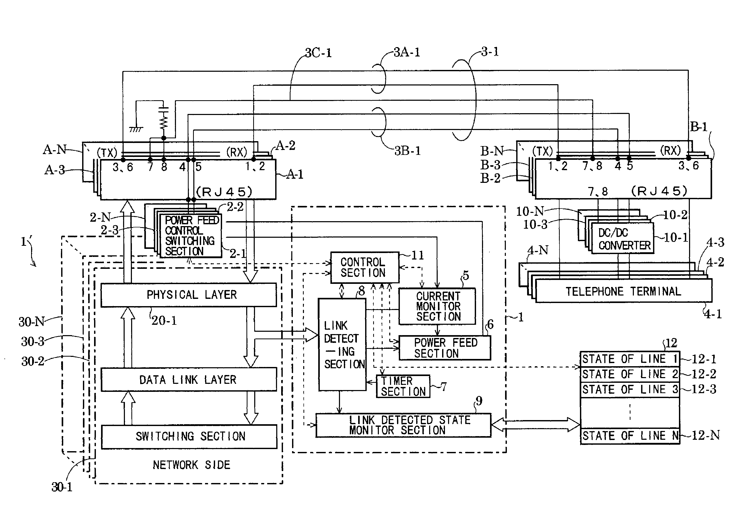
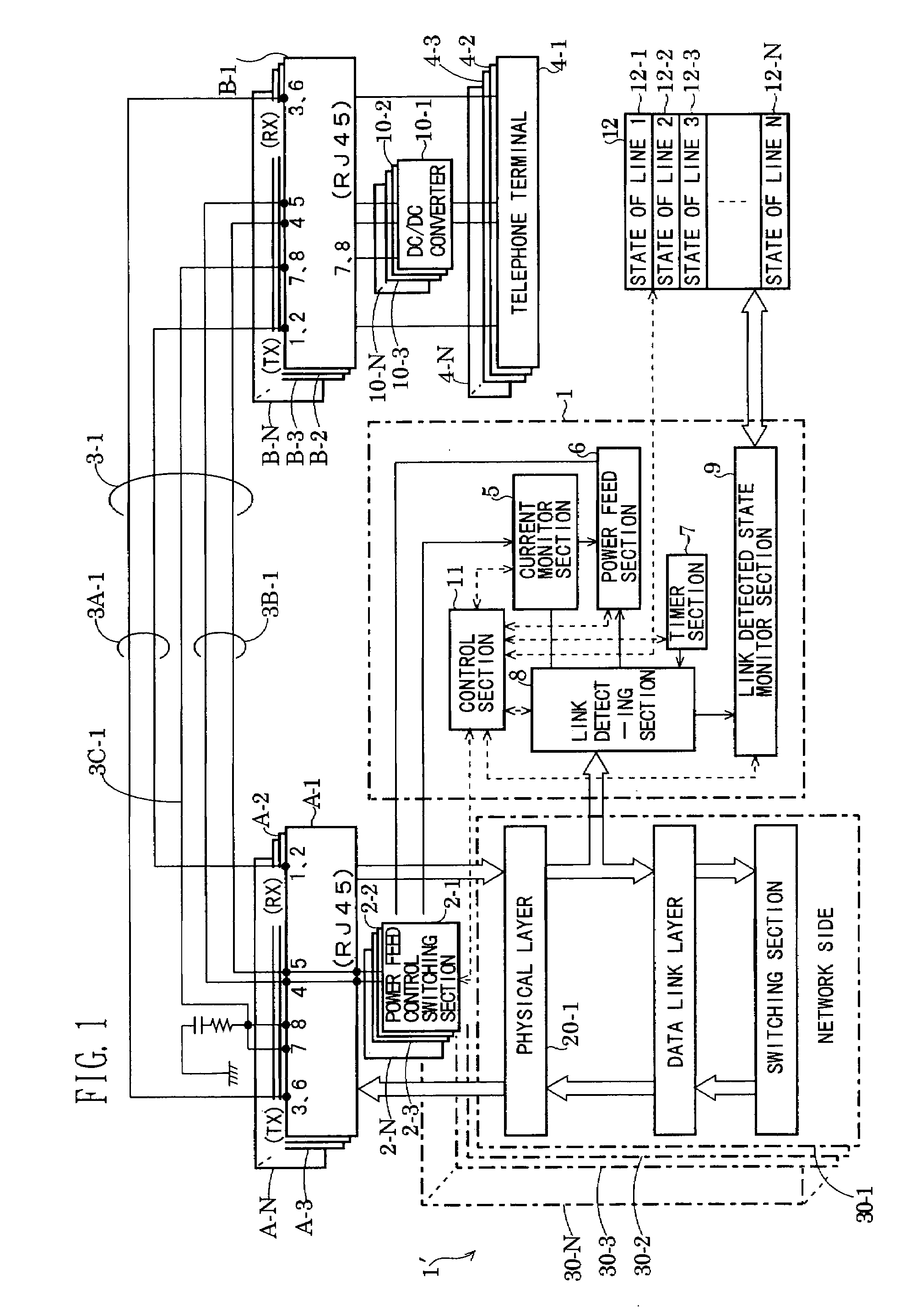
[0020]FIG. 1 shows the structure of the power feeding system according to the preferred embodiment of the present invention. In FIG. 1, the power feeding system comprises a HUB 1′ as a line concentrator having ports 30-1 to 30-N, cables 3-1 to 3-N (N is the maximum number corresponding to the number of the ports 30-1 to 30-N, which will be also applied to other components described hereinafter), terminals 4-1 to 4-N, connectors A-1 to A-N, and connectors B-1 to B-N. Although all the terminals 4-1 to 4-N are shown to be telephone terminals in FIG. 1 for facilitating explanation of the power feeding system, some of the terminals may be terminals other than the telephone terminals, of course. The terminals 4-1 to 4-N are connected to the HU...


PUM


Abstract

Terminals are connected via cables in a star-shaped fashion with respect to a HUB in a LAN. Each of the cables includes therein signal lines and power feed lines. The HUB includes therein a power feed section. The power feed section and the power feed lines of each cable are connected to measure a value of current which flows in the power feed lines. If it is judged based on the measured current value that the terminal connected to the corresponding cable is a telephone terminal, the power feeding to the corresponding power feed lines is continued. On the other hand, if the terminal is judged to be a terminal other than the telephone terminal, the power feeding is stopped.

Description

[0001]This application is a continuation of U.S. application Ser. No. 09 / 352,332, filed Jul. 13, 1999 now U.S. Pat. No. 6,681,013.BACKGROUND OF THE INVENTION[0002]1. Field of the Invention[0003]The present invention relates to a system for feeding the power to a telephone terminal / terminals connected to a LAN (Local Area Network).[0004]2. Description of the Related Art[0005]In recent years, the so-called downsizing has been rapidly developed in the information processing field. For facilitating the downsizing, technology of LAN's has been developed for achieving distributed processing or horizontal distributed processing using a plurality of work stations or personal computers. Simultaneously, technology of LAN telephone terminals adapted for the LAN environment has also been developed. In this case, it is important to realize a power feeding system for the LAN telephone terminals.[0006]Specifically, in transmission lines forming the LAN environment, data signals are flowing. Thus, ...

Claims


Application Information

Patent Timeline
Patent Type & Authority Patents(United States)
IPC IPC(8): H04M1/00H04M9/00H04M19/00H04L12/10H04L12/44H04M11/00
CPCH04L1/22H04L12/10H04L12/44
Inventor MIYAMOTO, KATSUHIKO
Owner OKI ELECTRIC IND CO LTD
Learn More