Filter assembly of washing machine

a technology for washing machines and filters, applied in the field of washing machines, can solve the problems of noise, lowering the drain capacity of washing machines, and affecting the operation of the drain pump,

Inactive Publication Date: 2007-07-17
LG ELECTRONICS INC
View PDF9 Cites 17 Cited by
  • Summary
  • Abstract
  • Description
  • Claims
  • Application Information

AI Technical Summary

Benefits of technology

[0019]In another aspect of the present invention, there is provided a filter assembly of a washing machine including a filter case comprising a tube having inlet and outlet on a circumference, a partition wall provided in the tube to partition an internal space of the tube into first and second chambers communicating with the inlet and outlet, respectively, and the opening perforating the partition wall and a filter comprising a cap fitted to the filter case to be fixed thereto, a shaft extending from the cap toward the opening, and a plate provided at an end of the shaft to be disposed in front of the opening with a predetermined gap to prevent a heavy particle from passing through the opening wherein the heavy particle is gathered in a central area by a centrifugal force when water flowing in the first chamber via the inlet whirls to pass through the opening.

Problems solved by technology

In such a case, such particles as lint and the like are frequently fitted to an impeller of the drain pump or a motor shaft, whereby drain capacity of the washing machine is lowered, noise takes place, and the drain pump can be out of order.

Method used


Image

  • Filter assembly of washing machine
  • Filter assembly of washing machine
  • Filter assembly of washing machine

Examples


first embodiment

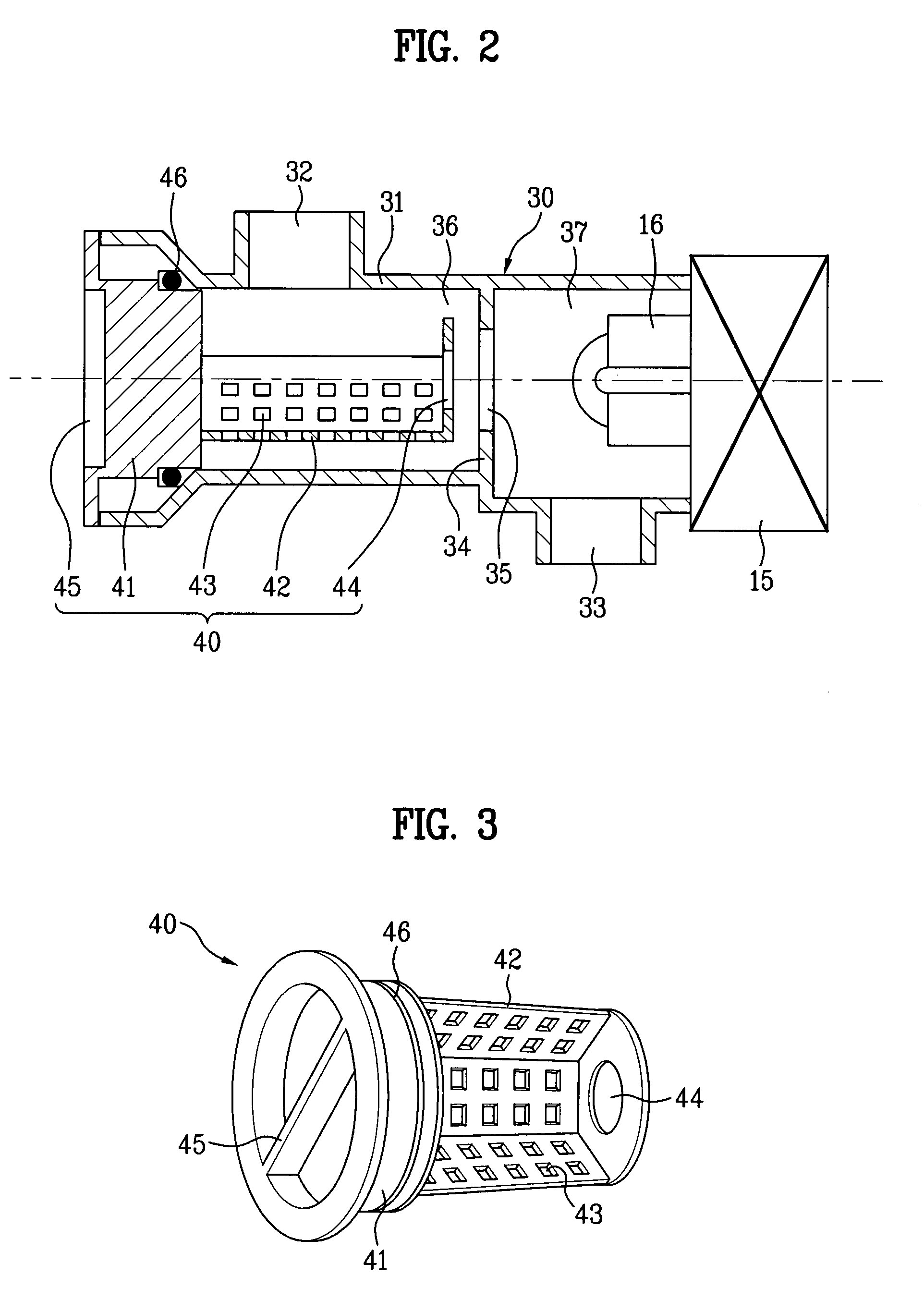
[0035]Referring to FIG. 2, a filter assembly according to the present invention includes a filter case 30 and a filter 40.

[0036]The filter case 30 includes a tube 31, a partition wall 34, and an opening 35.

[0037]Both ends of the tube 31 are open, and an inlet 32 and an outlet 33 are provided on an outer circumference of the tube 31. The inlet 32 communicates with a tub (not shown in the drawing). On draining, water in the tub and the drum 32 flows into the tube 31 via the inlet 32.

[0038]The partition wall 34 is provided in the tube 32 to partition an internal space of the tube 31 into a first chamber 36 and a second chamber 37. The first chamber 36 communicates with the inlet 32 and the second chamber 37 communicates with the outlet 33. Of course, the both open ends of the tube 31, as shown in FIG. 2, communicate with the first and second chambers 36 and 37, respectively.

[0039]The opening 35 is provided to perforate the partition wall 34. The water flowing into the first chamber 36 ...

second embodiment

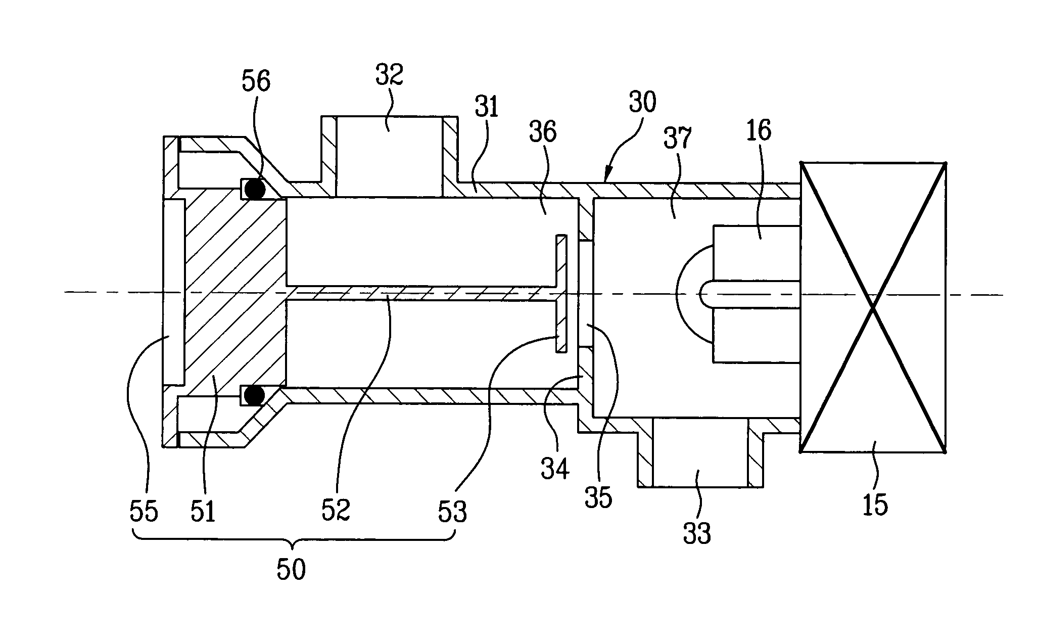
[0052]FIG. 4 is a cross-sectional view of a filter assembly according to the present invention and FIG. 5 is a perspective view of the filter assembly in FIG. 4, in which like elements are indicated using the same or similar reference designations where possible.

[0053]Referring to FIG. 4 and FIG. 5, a filter assembly according to a second embodiment of the present invention includes a filter case 30 and a filter 50. A structure of the filter case 30 is similar or equivalent to that of the first embodiment of the present invention, thereby being skipped in the following. And, a characterized structure of the filter case 30 of the filter assembly according to the second embodiment of the present invention is explained as follows.

[0054]In the filter assembly according to the second embodiment of the present invention, a technical background of removing particles is similar to that of a cyclone type vacuum cleaner which filters dust and particles heavier than air using a centrifugal for...


PUM

PropertyMeasurementUnit
centrifugal forceaaaaaaaaaa
sizeaaaaaaaaaa
frictional forceaaaaaaaaaa

Abstract

A filter assembly for a washing machine is provided which uses a simple structure to separate dirt and/or particles from washing water using. The filter assembly includes a filter case with an inlet and an outlet each positioned along its circumference, and an opening within the filler case which allows for communication between the inlet and outlet. A filter is provided in the filter case, the filter having a plate disposed in front of the opening to prevent particles from passing through the opening. Rather, the heavy particles are gathered in a central area of the filter by a centrifugal force generated by the water flowing in the filter case.

Description

[0001]This application claims the benefit of Korean Application(s) No. 10-2002-0075001 filed on Nov. 28, 2002, which is / are hereby incorporated by reference.BACKGROUND OF THE INVENTION[0002]1. Field of the Invention[0003]The present invention relates to a washing machine, and more particularly, to a filter assembly of a washing machine having a simple structure to separate dirt or particles involved in washing water using a centrifugal force.[0004]2. Discussion of the Related Art[0005]Generally, a washing machine is an apparatus for removing contaminating particles attached to the laundry, e.g., clothes, linen, etc., using interaction between water and detergent.[0006]Such a washing machine is categorized into an agitator type, a pulsator type and a drum type. The agitator type washing machine rotates a washing rod protruding upward from a bottom center of a tub clockwise and counterclockwise. The pulsator type washing machine performs a washing step using a frictional force between...

Claims


Application Information

Patent Timeline
Patent Type & Authority Patents(United States)
IPC IPC(8): D06F39/10D06F39/08
CPCD06F39/085D06F39/10C02F2307/12
Inventor KIM, KEONKANG, YU BEOMJE, SANG MAN
Owner LG ELECTRONICS INC
Why Eureka
Try Eureka