Electroluminescent lighting system

a technology of electroluminescent lighting and lighting system, which is applied in the direction of lighting and heating apparatus, discharge tube luminescnet screens, instruments, etc., can solve the problems of increasing the intensity of the panel over time, affecting the effect of the lighting effect, so as to reduce the flaring problem

Inactive Publication Date: 2007-07-24
NOKIA CORP
View PDF19 Cites 46 Cited by
  • Summary
  • Abstract
  • Description
  • Claims
  • Application Information

AI Technical Summary

Benefits of technology

[0019]The inventions described below provide EL lighting systems for use in portable or mobile electric devices. In accordance with one embodiment, the present invention relates to a flare reducing lighting system comprising a driver circuit including a source of AC voltage and an electroluminescent panel with a plurality of panel regions configured to emit visible light when AC voltage is applied thereto. Each panel region has a given capacitance and is selectively connectable to the source of AC voltage. A substitute capacitor is associated with each panel region. The substitute capacitor has a capacitance that is substantially equal to the capacitance of the associated panel region and is connected to the source of AC voltage when the associated panel region is not connected to the source of AC power and vice versa. Thus, the capacitance of the load connected to the driver circuit does not substantially vary when EL panel regions are switched on and off. An exact match in capacitance between the EL panel section and the substitute capacitor is not required to reduce the flaring problem.
[0022]The panel regions and the substitute capacitors are preferably formed in a single thin film. By forming the substitute capacitors in the same film as the panel region, a compact, and production friendly construction is obtained. If similar dielectric materials are selected for both the emission and the layer forming the substitute capacitor the substitute capacitor is automatically closely matched to the capacitance of the panel region.
[0024]The emission layer is compressed when the electrodes with the emission layer there between are charged and the emission layer is decompressed when the electrodes with the lighting layer there between are discharged. The same applies to the elimination layer. The rate of compression of emission layer upon charging is preferably substantially equal to the rate of decompression of the lower elimination layer upon discharging and vice versa. Simultaneous compression and decompression of the emission layer and the elimination layer substantially offset one another's changes in thickness. The emission layer and the elimination layer are operated in opposite phase and the resulting changes in layer thickness compensate one another. Thus, the overall thickness of the active panel remains substantially constant and virtually no noise is produced by the operating panel.

Problems solved by technology

As an EL panel ages, the capacitance of the lamp decreases, and without compensation, this decrease in capacitance causes the intensity of the panel to dim over time since the impendence of the drive circuit no longer matches the load.
One of the problems with EL panels that comprise a plurality of panel regions is—as experienced by the inventors—emission intensity changes of lit panel regions when other panel regions are switched on or off.
The driver circuit disclosed in U.S. Pat. No. 4,611,150, that may partially reduce these undesired effects, is however complex, expensive and undesirable from an economic point of view in mass produced articles.
Another inherent problem with EL panels is that in operation, such devices emit acoustic energy within the audible range of sound waves, producing an associated objectionable buzz or hum.
This audible noise is particularly problematic in applications such as mobile phones, which in operation are held in very close proximity to the user's ear and in which any appreciable noise interferes with the use and operability of the device.
This in turn reduces the rate of physical deformation of the lamp electrodes resulting from opposite electrical charges, and reduces the audible output of the EL panel.
The solution described in U.S. Pat. No. 5,789,870, however, requires a complex electronic driving circuit, comprising a plurality of operational amplifiers, transistors, diodes, resistors, and capacitors.
The solution described in U.S. Pat. No. 6,563,271, however, requires a complex electronic driving circuit, and is less useful for EL panels in which panel regions are selectively switched on and off, since the noise can only be canceled effectively if an even number of panel regions is active.

Method used


Image

  • Electroluminescent lighting system
  • Electroluminescent lighting system
  • Electroluminescent lighting system

Examples


Embodiment Construction

)

[0038]The EL panels according to the present invention can advantageously be used in combination with mobile communication terminals. Such a terminal in the form of a hand portable phone, preferably a cellular / mobile phone, will be described hereafter.

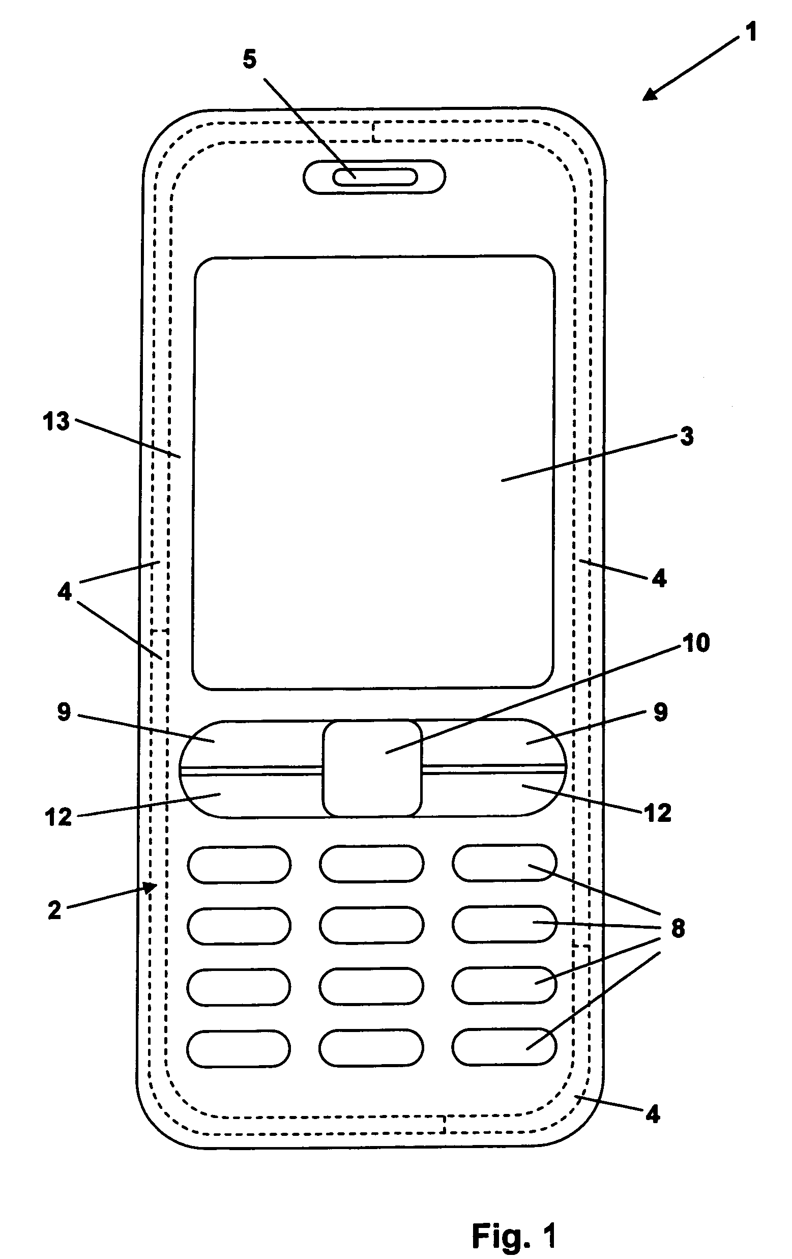
[0039]FIG. 1 shows a mobile phone according to the invention. The phone 1 comprises a user interface having a keypad 2, a display 3, an on / off button (placed on top, not shown), a speaker 5 (only the openings are shown), and a microphone 6 (not shown, opening for the microphone is placed on the bottom of the phone). The phone 1 according to the preferred embodiment is adapted for communication via a cellular network, such as the GSM 900 / 1800 / 1900 MHz of the G3 network.

[0040]The keypad 2 has a first group of keys 8 as alphanumeric keys, by means of which the user can enter a telephone number, write a text message (SMS), write a name (associated with the phone number), etc. Each of the twelve alphanumeric keys 8 is provided with a figur...


PUM


Abstract

Electroluminescent panels for use in battery operated devices include a driver circuit and a plurality of panel regions having a capacitance. Each panel region has a substitute capacitor with a capacitance substantially equal to the capacitance of the panel region concerned. The driver circuit switches between the panel region and the substitute capacitor, switching the panel region on and off. The capacitance of the load on the driver circuit does not change. The electroluminescent panels can have an elimination layer that eliminates noise produced by the emission layer in operation caused by changes in emission layer thickness. The elimination layer is added to the panel and operated in phase opposition to the emission layer. Changes in layer thickness occurring in operation in the emission layer are offset by changes in thickness in the elimination layer. Thus, the overall thickness of the panel is constant.

Description

BACKGROUND OF THE INVENTION[0001]1. Field of the Invention[0002]The inventions relate to electroluminescent lighting.[0003]2. Brief Description of Related Developments[0004]Electroluminescent panels are thin planar light emitting devices commonly employed to provide backlighting in a variety of the display applications, including for example laptop computers, personal digital assistants, wristwatches and a myriad of other electronic devices. One product for which electroluminescent panels are becoming increasingly prevalent is mobile phones. Generally, many of the mobile phones which are currently being produced have large backlit displays. The large displays allow a user to operate the telephone by selecting options from a displayed menu, or to receive and display data via a wireless Internet service.[0005]Electroluminescent (EL) panels are now also being used to light up cover parts of the phone, e.g. for lighting up the rear cover for signaling or fun. Hereto, an EL panel (thin f...

Claims


Application Information

Patent Timeline
Patent Type & Authority Patents(United States)
IPC IPC(8): F21V9/16G09G3/10H04M1/02H04M1/22H05B44/00
CPCH04M1/22H05B33/08H04M1/0283Y02B20/325Y02B20/30H05B44/00
Inventor BURGER, VICTORVAN WALSTIJN, BARTHOLOMEUS GERARDUS GOSEWINUS
Owner NOKIA CORP
Why Eureka
Try Eureka