Medical balloon catheter

a technology of balloon catheter and helical tube, which is applied in the field of medical balloon catheter, can solve the problems of increased production cost, increased number of production process operations, and difficult to increase the kink resistance of the entire catheter shaft, so as to reduce the diameter of this portion, reduce the discontinuity of flexibility in the vicinity of the balloon, and improve the process stability

Inactive Publication Date: 2007-07-24
KANEKA CORP
View PDF17 Cites 14 Cited by
  • Summary
  • Abstract
  • Description
  • Claims
  • Application Information

AI Technical Summary

Benefits of technology

[0047]Further, the medical balloon catheter in accordance with the present invention has a structure in which the proximal end of an X ray impermeable ring is abutted against and fixed to the boundary portion of the proximal end side and the small-diameter portion on the distal end side of the tube for passing a guidewire inside thereof. With such a structure, discontinuity of flexibility in the vicinity of the balloon can be reduced and the above-mentioned problem is resolved.
[0048]Further, the medical balloon catheter in accordance with the present invention has a structure in which the tube constituting the outer surface of the catheter is composed of a material that can be fused with the balloon and is fused and arranged on the proximal end side of the balloon. With such a structure, because no adhesive layer is formed, the distal end side of the balloon is flexible and discontinuity of flexibility can hardly occur therein. Therefore, the above-mentioned problem is resolved. An additional advantage from the production standpoint is gained when the above-described structures are employed in balloon catheters of a rapid exchange type, in which the guidewire tube is limited to a range from the distalmost end of catheter to the intermediate part of the outer tube, because the guidewire inlet portion can be formed by fusing the outer tube with the guidewire tube, process stability is superior to that of the molding process using adhesive bonding or the like, and the diameter of this portion can be reduced.

Problems solved by technology

However, when the outer tube itself has a high kink resistance, or when a high kink resistance is provided with a reinforcing member such as a metal wire and the like disposed inside the outer tube, the rigidity of the outer tube is locally increased, but the kink resistance of the entire catheter shaft is difficult to increase.
Further, the problem associated with providing an additional component, as shown in the embodiment of the prior art technology in which a wire braid was embedded in a plastic outer tube, is that the number of production process operations was increased and production cost was raised.

Method used


Image

  • Medical balloon catheter
  • Medical balloon catheter
  • Medical balloon catheter

Examples


embodiment 1

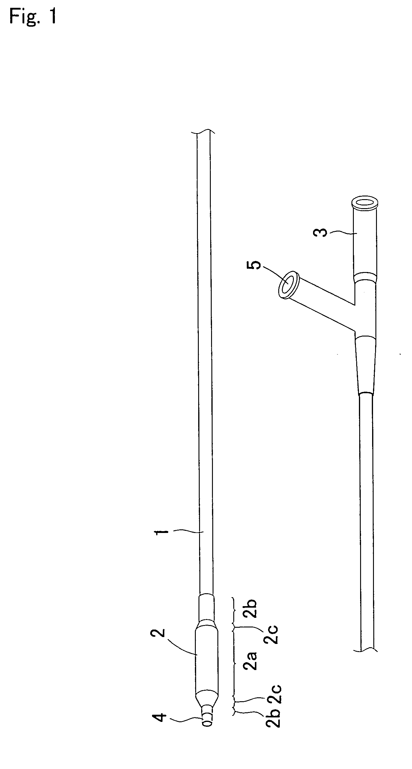
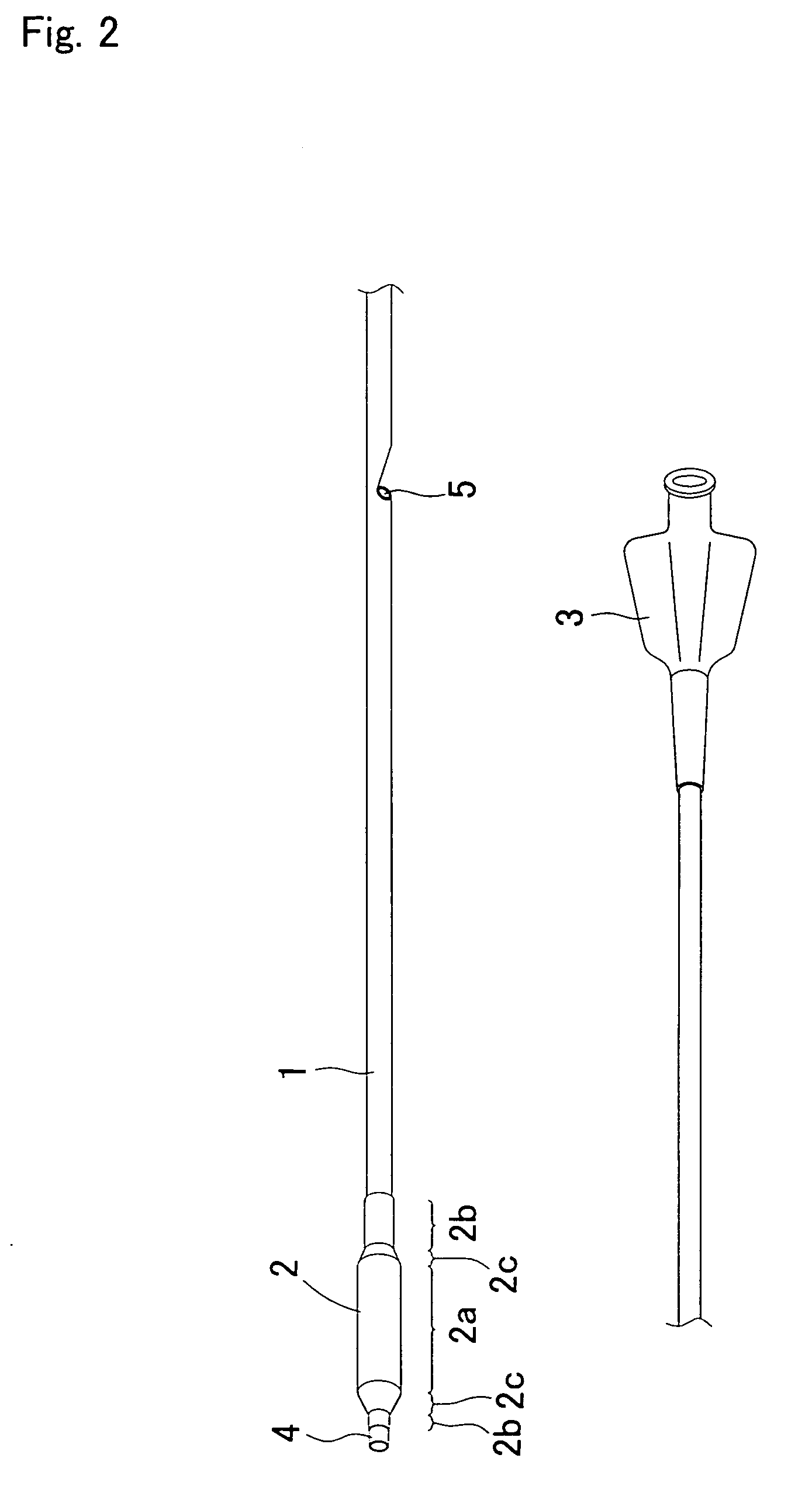
[0123]A tubular parison (inner diameter 0.43 mm, outer diameter 0.89 mm) was fabricated by an extrusion molding method by using a polyamide elastomer (trade name: PEBAX7233SA01, manufactured by Elf Atochem Co.). Then, a balloon with an outer diameter of a straight tube portion of 3.0 mm was fabricated by a biaxial stretching and blowing method by using the parison.

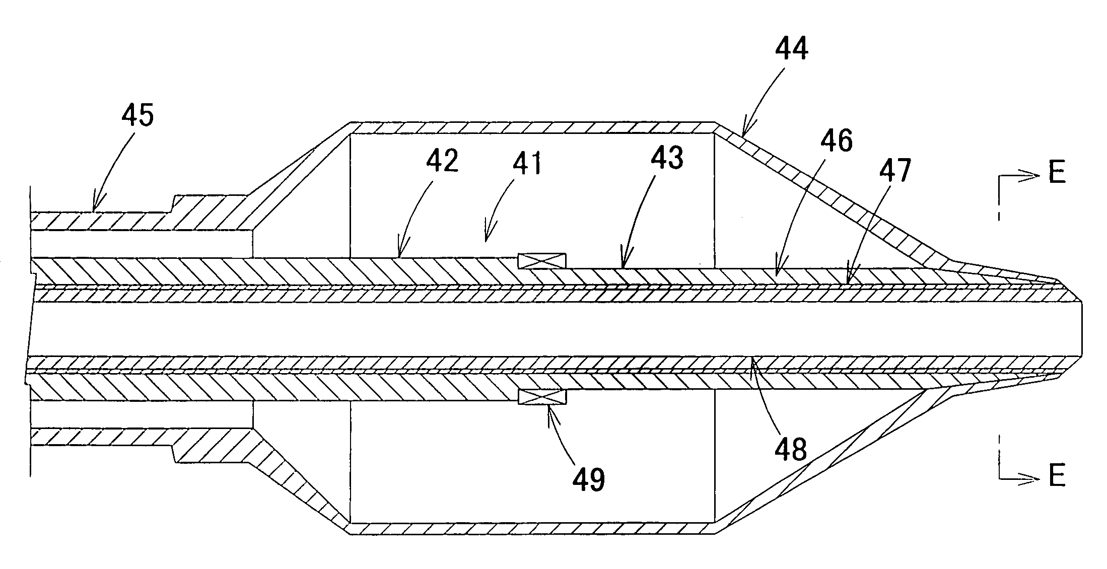
[0124]The inner tube (inner diameter 0.42 mm, outer diameter 0.56 mm) and an outer tube (inner diameter 0.71 mm, outer diameter 0.88 mm) were fabricated by extrusion molding by using a polyamide elastomer (trade name: PEBAX7233SA01, manufactured by Elf Atochem Co.). The balloon and outer tube were joined by thermal fusion. Then, the inner tube and outer tube were arranged so as to obtain a coaxial double-wall tubular configuration and the balloon and inner tube were joined by thermal fusion. Notches with a length of half a perimeter in the circumferential direction were provided in part of the outer tube, the inner tube wa...

embodiment 2

[0128]Fabrication was conducted in the same manner as in Embodiment 1, except that slits with a width of 0.3 mm and a spacing of 2 mm were provided with a length of half a perimeter in the circumferential direction by laser processing on a distal end portion (with a length of 50 mm) of a proximal end shaft, as shown in FIG. 12.

embodiment 3

[0129]Fabrication was conducted in the same manner as in Embodiment 1, except that four round holes with a diameter of 0.4 mm were produced with equal spacing on the same circumference by laser processing on a distal end portion (with a length of 40 mm) of a proximal end shaft, the distance between the holes in the axial direction being 0.5 mm, as shown in FIG. 19.


PUM

PropertyMeasurementUnit
diameteraaaaaaaaaa
outer diameteraaaaaaaaaa
widthaaaaaaaaaa

Abstract

The medical balloon catheter of the present invention comprises a catheter shaft composed of a distal end shaft and a proximal end shaft and a balloon on the distal end of the distal end shaft, wherein the proximal end shaft is composed of a single member and the distal end portion of the proximal end shaft is lower in rigidity than the other parts thereof. The present invention also provides a medical balloon catheter having a structure in which a tube for passing a guidewire inside thereof is arranged so as to pass inside the balloon and the balloon and tube are fused together in the vicinity of the distal end of the catheter, wherein the ratio of the outer diameter of the small-diameter portion on the distal end side of the tube to the outer diameter of the proximal end portion is no less than 0.85.

Description

TECHNICAL FIELD[0001]The present invention relates to a medical balloon catheter used for medical applications, and more particularly to a medical balloon catheter for percutaneous angioplasty (PTA: Percutaneous Transluminal Angioplasty, PTCA Percutaneous Transluminal Coronary Angioplasty, and the like) during realization of peripheral angioplasty, coronary angioplasty, valvular angioplasty, and the like.BACKGROUND ART[0002]Percutaneous angioplasty using medical balloon catheters has been widely used for dilation therapy of stenoses or blocked portions of vascular cavities and for restoration or improvement of blood flow in coronary artery, peripheral blood vessels, and the like. In a typical medical balloon catheter, a balloon that can be inflated or contracted by internal pressure adjustment is joined to the distal end portion of a catheter shaft, and an inner cavity (guidewire lumen) for passing a guidewire and an inner cavity (inflation lumen) for supplying a pressure fluid for ...

Claims


Application Information

Patent Timeline
Patent Type & Authority Patents(United States)
IPC IPC(8): A61M29/00A61M25/00A61M29/02
CPCA61M25/0054A61M25/104A61M25/0045A61M25/00
Inventor NISHIDE, TAKUJIFUKAYA, KOHEIHASHIBA, MASATO
Owner KANEKA CORP
Why Eureka
Try Eureka