Angular velocity detector

a technology of angular velocity and detector, applied in the direction of acceleration measurement using interia force, turn-sensitive devices, instruments, etc., can solve the problems of insufficient support of angular velocity detecting elements using adhesives, simple reduction of the adhesion area of adhesives, etc., to prevent a reduction in the detection accuracy of angular velocity

Inactive Publication Date: 2007-07-31
DENSO CORP
View PDF6 Cites 22 Cited by
  • Summary
  • Abstract
  • Description
  • Claims
  • Application Information

AI Technical Summary

Benefits of technology

[0009]The inventors of the present application considered an angular velocity detector in which an angular velocity detecting element is laminated on a circuit substrate through an adhesive of a low Young's modulus, for preventing a reduction in the detecting accuracy of the angular velocity. Here, the circuit substrate is used for processing a signal from this angular velocity detecting element.
[0012]In view of the above problem, it is an object of the present invention to provide an angular velocity detector in which an angular velocity detecting element is laminated on a circuit substrate through an adhesive. The angular velocity detector reduces resonance frequency of a structural body by reducing an adhering area of the adhesive while easily and accurately performing a wire bonding between the angular velocity detecting element and the circuit substrate.
[0014]Because the adhesive is partially arranged on the base substrate, the bonding area of the adhesive can be made smaller, the resonance frequency of this detector can be effectively reduced, and an external acceleration component of a vibration frequency area of the vibrating body, transmitted to the vibrating body, is reduced, and the angular velocity can be accurately detected. Furthermore, because the adhesive is partially arranged on the first surface of the base substrate at least at a portion corresponding to a bonding portion of the bonding wire on the second surface of the base substrate, wire bonding of the bonding wire can be easily performed.
[0015]Alternatively, the adhesive is partially arranged on the first surface of the base substrate in an arrangement area, and the bonding wire is connected to the angular velocity detecting element at a position within a projecting area on the second surface of the arrangement area of the adhesive. In this case, the wire bonding of the bonding wire can be easily accurately performed.
[0016]For example, the angular velocity detecting element is arranged above the circuit substrate, and the adhesive is partially provided on the first surface of the base substrate below the bonding portion of the bonding wire in the base substrate. In this case, the wire bonding can be more easily performed. Furthermore, a plurality of the bonding wires can be arranged at different bonding portions in the base substrate. In this case, the adhesive is partially arranged on the first surface of the base substrate at least at portions corresponding to the bonding portions of the bonding wires in the base substrate.
[0017]The adhesive can be arranged at a peripheral portion of the first surface of the base substrate symmetrically, to support the angular velocity detecting element. In this case, it can prevent the base substrate from being inclined, and the wire bonding can be easily accurately performed.

Problems solved by technology

However, when the adhering area of the adhesive is simply reduced, the following problems are caused.
Further, when the adhering area of the adhesive is simply reduced, the supporting of the angular velocity detecting element using the adhesive becomes insufficient.
Therefore, when the wire bonding is performed, there is a possibility that the substrate of the angular velocity detecting element is inclined and wire bonding may be not performed.

Method used


Image

  • Angular velocity detector
  • Angular velocity detector
  • Angular velocity detector

Examples


first embodiment

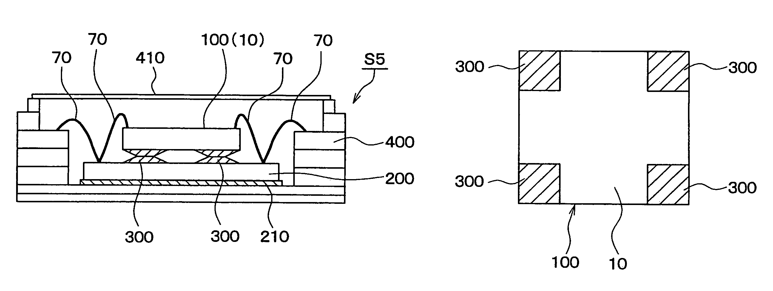
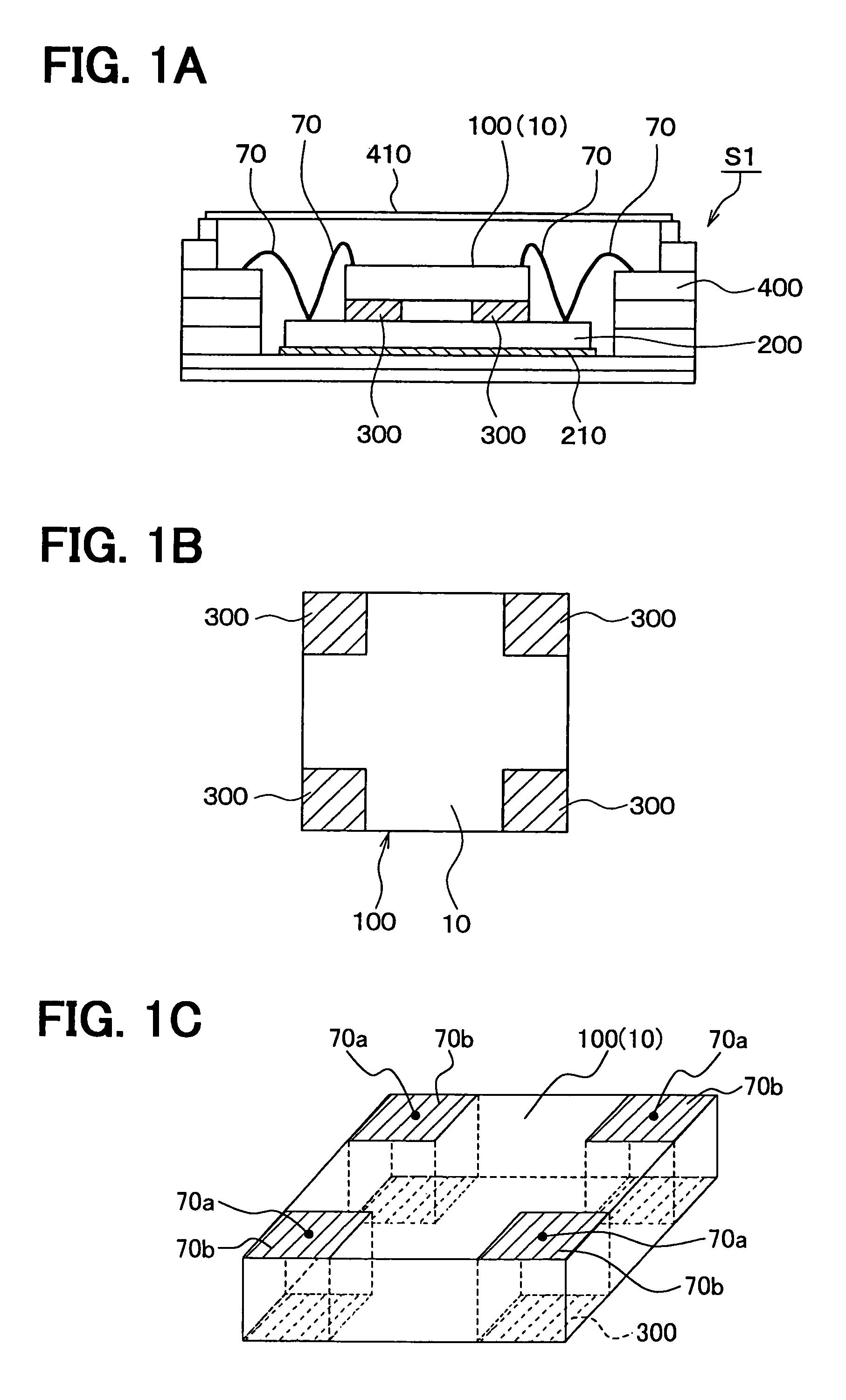
[0026]As shown in FIG. 1, an angular velocity detector S1 of this embodiment includes an angular velocity detecting element 100, a circuit substrate 200 and a package 400 for accommodating the angular velocity detecting element 100 and the circuit substrate 200. The circuit substrate 200 is fixed to the package 400. The angular velocity detector S1 is constructed as a structural body in which the angular velocity detecting element 100 is laminated on the circuit substrate. 200 through an adhesive 300.

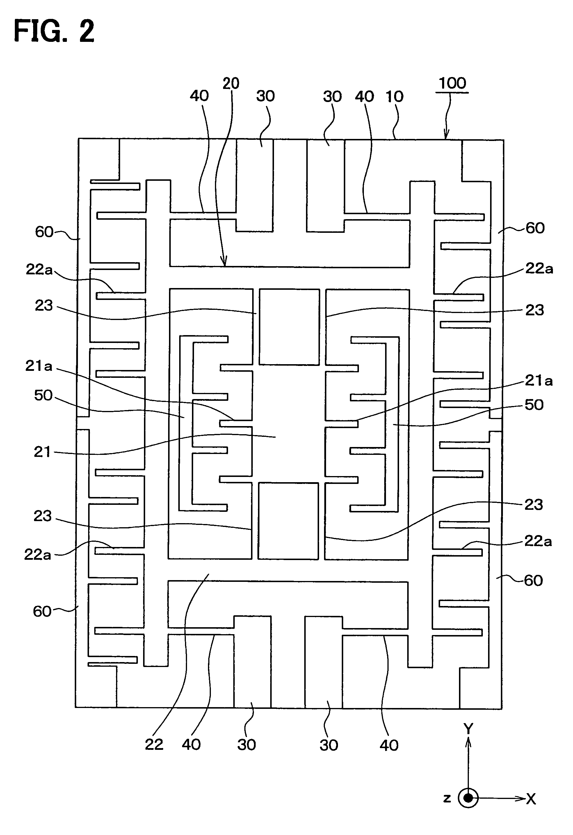
[0027]First, the angular velocity detecting element 100 will be described with reference to FIG. 2. The angular velocity detecting element 100 has a substrate 10 (base substrate) such as a semiconductor substrate, etc., and is formed by performing well-known micro machine processing with respect to this substrate 10.

[0028]For example, a rectangular SOI (silicon-on-insulator) substrate can be used as the substrate 10. The rectangular SOI can be formed by sticking a second silicon layer a...

second embodiment

[0068]This embodiment differs from the above first embodiment in that the arranging pattern of the adhesive 300 is changed. This difference will be centrally described.

[0069]In the above first embodiment, in the substrate 10 of the angular velocity detecting element 100 formed in the rectangular plate shape, the adhesive 300 is arranged in the four corner portions of this substrate 10.

[0070]In contrast to this, in the second embodiment, as shown in FIG. 3B, in the substrate 10 of the angular velocity detecting element 100 formed in the rectangular plate shape, the adhesive 300 is arranged in two opposite side peripheral portions of the substrate 10.

[0071]Thus, the resonance frequency of the angular velocity detector, i.e., the structural body in the direction along the horizontal surface of this substrate 10 can be reduced by reducing the adhering area of the adhesive 300. Further, the peripheral portion connected to the bonding wire 70 in the substrate 10 of the angular velocity de...

third embodiment

[0074]This embodiment differs from the above embodiments in that the arranging pattern of the adhesive 300 is deformed. This difference will be centrally described.

[0075]In the above first and second embodiments, in the substrate 10 of the angular velocity detecting element 100 having the rectangular plate shape, the adhesive 300 is arranged in the four corner portions of this substrate 10, or is also arranged in both the opposite side portions in this substrate 10.

[0076]In contrast, in the third embodiment, as shown in FIGS. 4A and 4B, in the substrate 10 of the angular velocity detecting element 100 having the rectangular plate shape, the adhesive 300 is arranged in the entire periphery of a side portion of this substrate 10.

[0077]Thus, the resonance frequency of the angular velocity detector, i.e., the structural body in the direction along the horizontal surface of this substrate 10 can be reduced by reducing the adhering area of the adhesive 300. Further, the peripheral portion...


PUM


Abstract

An angular velocity detector includes an angular velocity detecting element having a vibrating body arranged in a base substrate to be vibrated on a surface horizontal with respect to the base substrate. The angular velocity detecting element detects an angular velocity around an axis perpendicular to the base substrate based on a vibration of the vibrating body. In the angular velocity detector, a circuit substrate is bonded to a first surface of the base substrate through an adhesive, and a second surface of the angular velocity detecting element is electrically connected to the circuit substrate through a bonding wire. Furthermore, the adhesive is partially arranged on the first surface of the base substrate at least at a portion corresponding to a bonding portion of the bonding wire on the second surface of the base substrate. Therefore, a wire bonding can be easily accurately performed.

Description

CROSS REFERENCE TO RELATED APPLICATION[0001]This application is based on Japanese Patent Application No. 2004-201815 filed on Jul. 8, 2004, the contents of which are incorporated herein by reference in its entirety.FIELD OF THE INVENTION[0002]The present invention relates to an angular velocity detector having an angular velocity detecting element in which a vibrating body is arranged in a substrate and an angular velocity around the axis perpendicular to the substrate is detected on the basis of vibration of this vibrating body. The angular velocity detector is formed by laminating an angular velocity detecting element on a circuit substrate through an adhesive.BACKGROUND OF THE INVENTION[0003]An angular velocity detecting element generally has a substrate such as a semiconductor substrate, etc., and a vibrating body able to be vibrated on a surface horizontal with respect to this substrate is formed.[0004]The vibrating body is operated and vibrated in a first direction on the hori...

Claims


Application Information

Patent Timeline
Patent Type & Authority Patents(United States)
IPC IPC(8): G01P9/04G01C19/56G01C19/5762G01C19/5769H01L29/84
CPCG01C19/5719H01L2224/48091H01L2224/73265H01L2924/16195H01L2924/19107H01L2924/00014
Inventor HIRANO, KENJI
Owner DENSO CORP
Why Eureka
Try Eureka