Pressurized steam boilers and their control

a technology of pressure steam boiler and pressure steam, which is applied in the direction of steam boiler components, liquid fuel feeders, fuel injecting pumps, etc., can solve the problems of high cost of false triggering of either the first low or the second low, inconvenient manual intervention, and potentially hazardous pressure steam boilers, so as to reduce the flow rate of steam into the boiler, improve the control of the burner and the boiler, and improve the effect of control

Inactive Publication Date: 2007-07-31
AUTOFLAME ENG
View PDF32 Cites 11 Cited by
  • Summary
  • Abstract
  • Description
  • Claims
  • Application Information

AI Technical Summary

Benefits of technology

[0033]the controlling of the flow rate of water into the boiler is such that it does reduce the rate of flow into the boiler.
[0034]Preferably, input and output signals relating to all the monitoring and controlling steps are passed into or transmit

Problems solved by technology

Pressurised steam boilers are potentially very hazardous because of the very high pressure that is maintained in the boiler and it is therefore essential for such boilers to have control systems that are extremely safe.
The requirement for manual intervention is inconvenient, but is regarded as a necessary safety requirement.
The false triggering of either the first low or second low is costly.
The effect of a false triggering at the first low is to turn off the burner; at best that may simply lead to less efficiency because the burner is switched completely off rather than simply being turned down to a lower firing rate; in a worst case, however, as will be explained below, the false triggering may lead to the burner being switched off at a time when the demand for heat in the boiler is especially high.
False triggering at the second low is more damaging because it is likely to last longer given that the burner can be rest

Method used


Image

  • Pressurized steam boilers and their control
  • Pressurized steam boilers and their control
  • Pressurized steam boilers and their control

Examples


Embodiment Construction

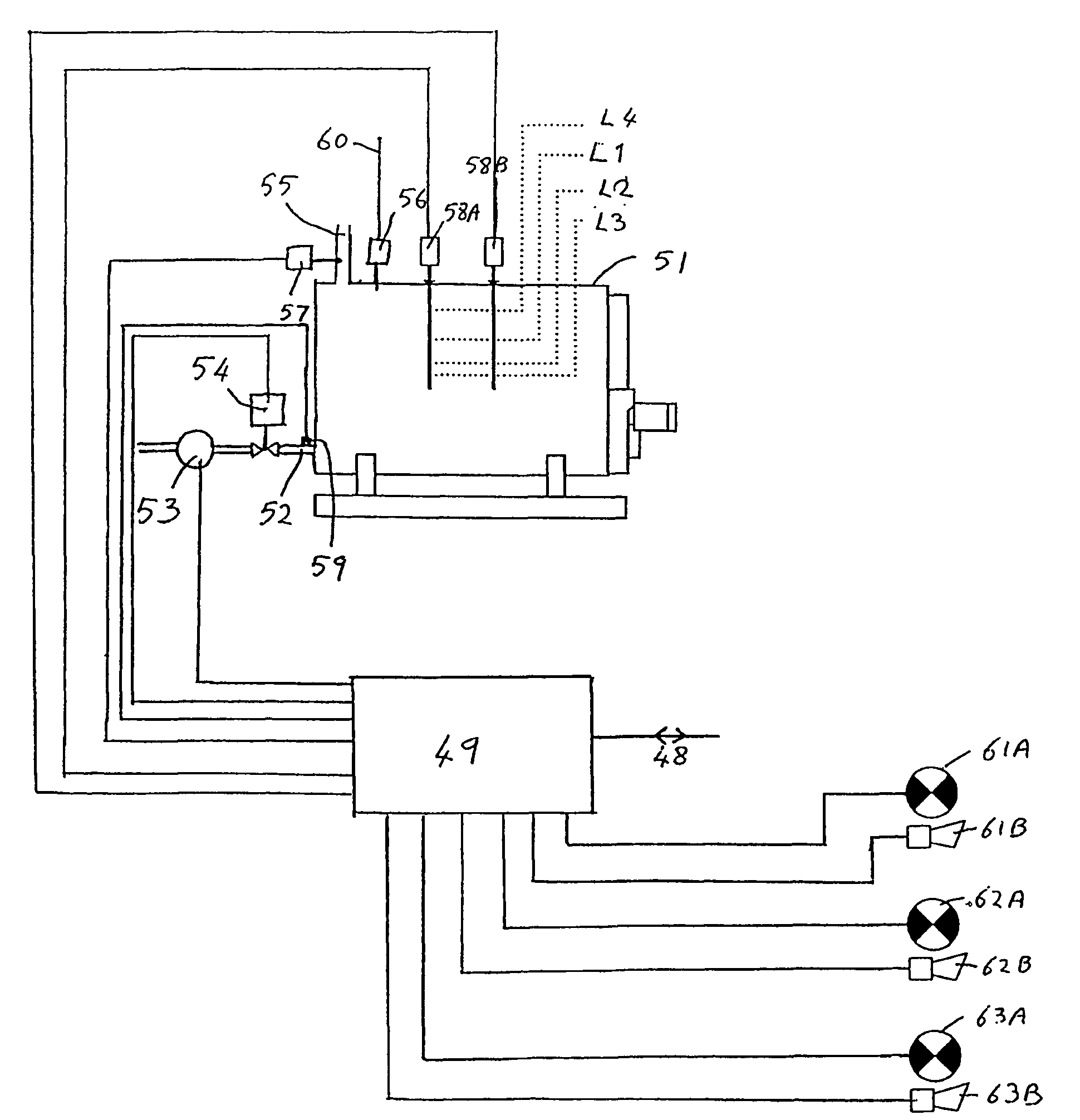
[0094]Referring first to FIG. 1, there is shown a burner 20 having a burner head 21, a combustion chamber 22 and a duct 23 for combustion products which comprise exhaust gases. As will be described below the duct 23 passes through a pressurized steam boiler; thereafter the exhaust gases are vented through a flue.

[0095]Air is fed to the burner head 21 from an air inlet 24, through a centrifugal fan 26 and then through an outlet damper 27. The burner head 21 is able to operate with either gas or oil as the fuel; gas is fed to the burner head from an inlet 28 via a valve 29 whilst oil is fed to the burner head from an inlet 30 via a valve 31.

[0096]A control unit 1 is provided for controlling the operation of the burner and boiler. The control unit 1 has a display 2, a proximity sensor 3 for detecting that a person is nearby, and a set of keys 5 enabling an operator to enter instructions to the control unit. The purpose of the proximity sensor is not relevant to the present invention an...


PUM


Abstract

A method of controlling the operation of a pressurised steam boiler (50) heated by a burner (20), which includes the steps of a) monitoring the level of water in the boiler (50), b) monitoring the pressure of steam in the boiler (50), c) monitoring the firing rate of the burner (20), and d) controlling the flow rate of water into the boiler (50) having regard to the signals resulting from a) and b) and, at least for some signal conditions, also having regard to signals resulting from c). The level of water is detected by a pair of capacitance probe assemblies (58A and 58B).

Description

CROSS-REFERENCE TO RELATED APPLICATIONS[0001]Not ApplicableSTATEMENT REGARDING FEDERALLY SPONSORED RESEARCH OR DEVELOPMENT[0002]Not ApplicableINCORPORATION-BY-REFERENCE OF MATERIAL SUBMITTED ON A COMPACT DISC[0003]Not ApplicableFIELD OF THE INVENTION[0004]The invention relates to pressurised steam boilers and their control, to a method and apparatus for detecting the level of water in a steam boiler and to a method and apparatus for assessing the mass flow of steam from a steam boiler.BACKGROUND OF THE INVENTION[0005]In a known arrangement of a pressurised steam boiler, water is fed into the boiler at a controlled rate and is heated in the boiler to convert the water to steam. The heat required to convert the water to steam is provided by a burner whose hot products of combustion are passed through ducts in the boiler and then exhausted. The steam boiler is controlled by a boiler control system, which receives information from sensors indicating inter alia the level of water in the ...

Claims


Application Information

Patent Timeline
IPC IPC(8): F22B37/46F22B37/78F22D5/30
CPCF22B37/78F22D5/30
Inventor KEMP, BRENDANNICHOLS, PAUL JAMES
Owner AUTOFLAME ENG
Why Eureka
Try Eureka