Touch screen apparatus and method therefore

a touch screen and apparatus technology, applied in the field of resistive touch screens, can solve the problems of inaccurate measurement, complex switching circuitry, and rapid switching between the conductive layers,

Active Publication Date: 2007-07-31
SYMBOL TECH LLC
View PDF14 Cites 49 Cited by
  • Summary
  • Abstract
  • Description
  • Claims
  • Application Information

AI Technical Summary

Problems solved by technology

One problem associated with resistive touch screens is the rapid switching between the conductive layers that is required to read the location at the point of contact.
The switching circuitry adds complexity to the design.
Moreover, the switching itself generates noise and voltage spikes that are troublesome to the electronics interfacing with the resistive touch screen and can also result in inaccurate measurements.
A second problem for a resistive touch screen is security when used for a secure transaction such as an ATM or point of sale verification.
In particular, there is the threat that the wires coupling the resistive touch screen to a main printed circuit board (system circuitry) could be monitored.
In addition, it is desirable to ensure secure data transfer by making eavesdropping between a touch screen device and other electronics difficult.

Method used


Image

  • Touch screen apparatus and method therefore
  • Touch screen apparatus and method therefore
  • Touch screen apparatus and method therefore

Examples


Embodiment Construction

[0022]The following detailed description is merely exemplary in nature and is not intended to limit the invention or the application and uses of the invention. Furthermore, there is no intention to be bound by any expressed or implied theory presented in the preceding technical field, background, brief summary or the following detailed description.

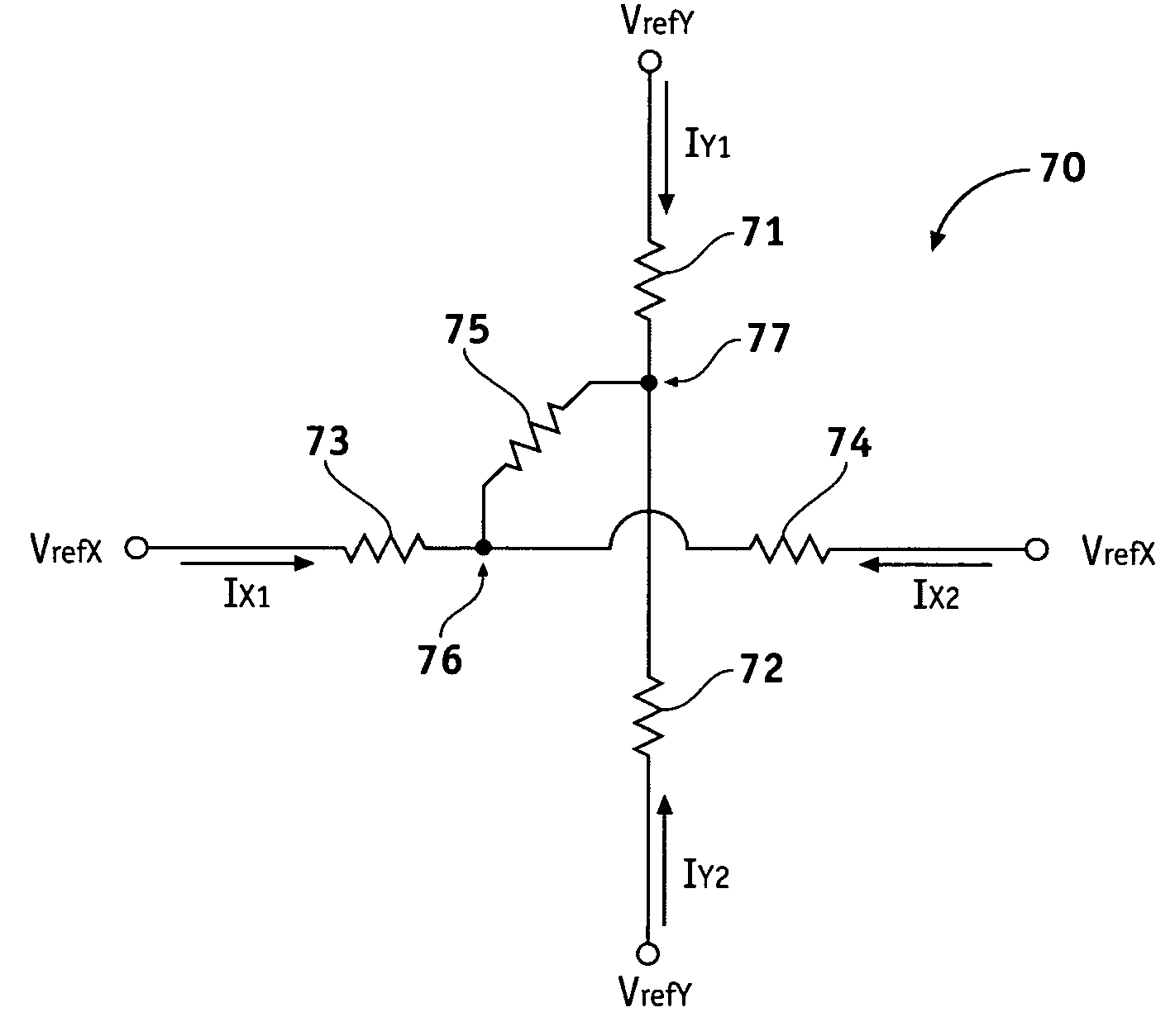
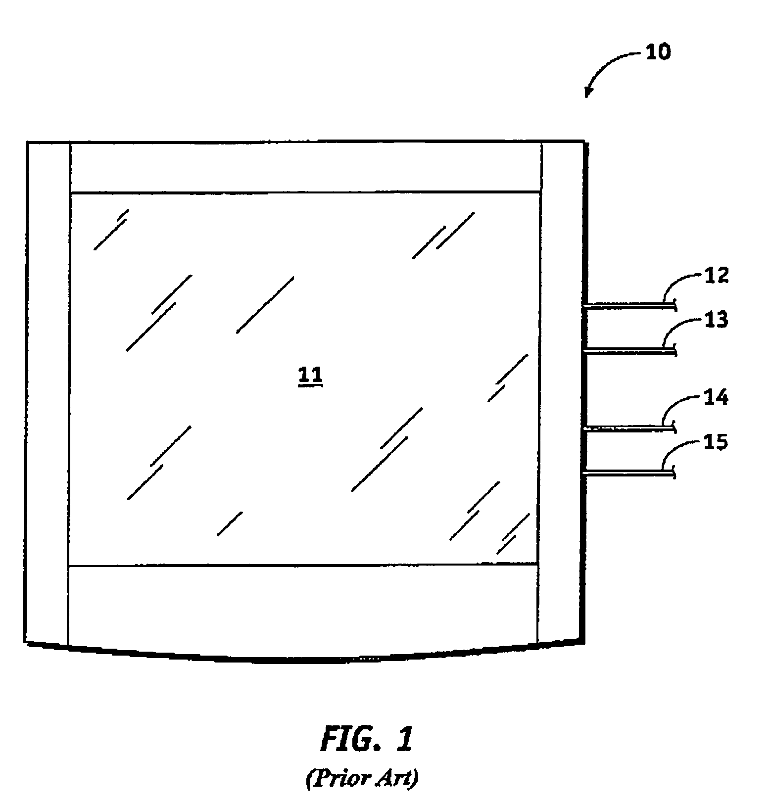
[0023]FIG. 1 is a top view of a prior art resistive touch screen 10. Resistive touch screen 10 comprises a transparent screen 11 that allows an underlying display (not shown) of an electronic system to be viewed. Wires 12, 13, 14, and 15 couple to resistive touch screen 10. Wires 12 and 13 couple to a first transparent conductive layer of resistive touch screen 10. Wires 14 and 15 couple to a second transparent conductive layer of resistive touch screen 10. The first and second transparent conductive layers are not in contact with each other under quiescent conditions. Although resistive touch screen 10 is shown having four wires there are...


PUM


Abstract

Methods and apparatus are provided for an apparatus for inputting data. The apparatus comprises a detection circuit for providing a first reference voltage to a first and a second electrode of a first conductive layer of a resistive touch screen and providing a second reference voltage to a first and a second electrode of a second conductive layer of the resistive touch screen. The detection circuit maintains the first and second reference voltages under quiescent conditions and when the first and second conductive layers couple together. The method includes applying substantially equal voltages to the first and second electrodes of the first conductive layer of the resistive touch screen. Substantially equal voltages are applied to the first and second electrodes of the second conductive layer of the resistive touch screen. Approximately zero current is conducted in the first and second conductive layers under quiescent conditions.

Description

TECHNICAL FIELD OF THE INVENTION[0001]The present invention generally relates to devices for inputting data to a system, and more particularly relates to resistive touch screens.BACKGROUND OF THE INVENTION[0002]Touch screen devices are widely used in devices such as ATM's, PDA's, computers, or point-of-sale devices to allow human input of information to an electronic system. A touch screen is a device that, when touched, generates signals identifying a location on a screen where contact was made. Underlying the touch screen is a visual medium such as a cathode ray tube or liquid crystal display tat displays an image. The signals from the touch screen are provided to the electronic system to relate the point of contact to the image on the display. In addition there are signature capture devices which do not include a display beneath the touch screen or touch pad.[0003]An example of an application where a touch screen is commonly used is in an ATM. The ATM is typically placed in a loc...

Claims


Application Information

Patent Timeline
Patent Type & Authority Patents(United States)
IPC IPC(8): G09G5/00G06F3/033G06F3/045G07F7/10
CPCG06F3/045
Inventor JAYANETTI, RUWANFERNANDO, LLAVANYA
Owner SYMBOL TECH LLC
Why Eureka
Try Eureka