
Oil ring for an internal combustion engine

a technology of internal combustion engine and oil flow control, which is applied in the direction of mechanical equipment, braking systems, transportation and packaging, etc., can solve the problems of increasing the oil consumption, limiting the limitation of known prior art technology in the optimization of friction losses and oil consumption, so as to reduce the inertia moment and reduce the friction

Inactive Publication Date: 2007-08-07
MAHLE COMPONENTS DE MOTORES DO BRASIL
View PDF24 Cites 6 Cited by
  • Summary
  • Abstract
  • Description
  • Claims
  • Application Information

AI Technical Summary

Benefits of technology

[0040]The general object of the present invention is to provide an oil ring for internal combustion engines having high conformability and optimized specific pressure to provide high oil scraping efficiency without increasing the friction losses.
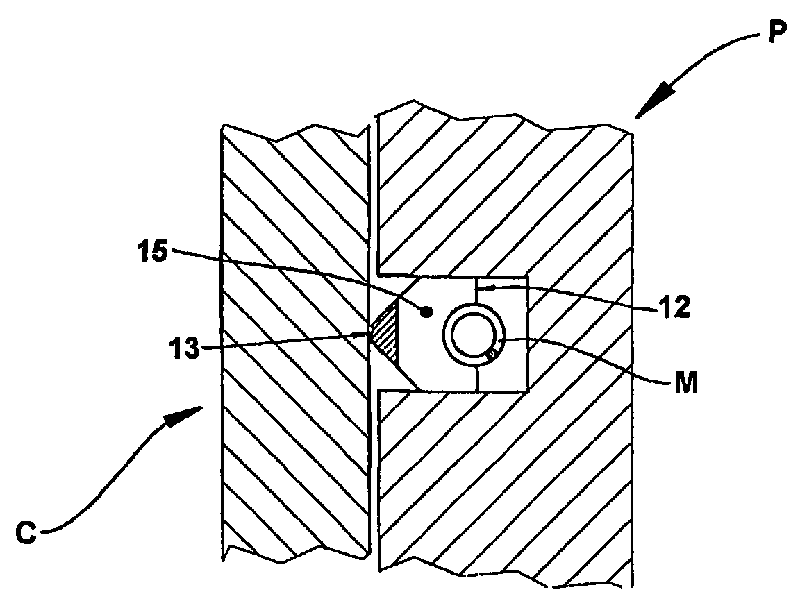
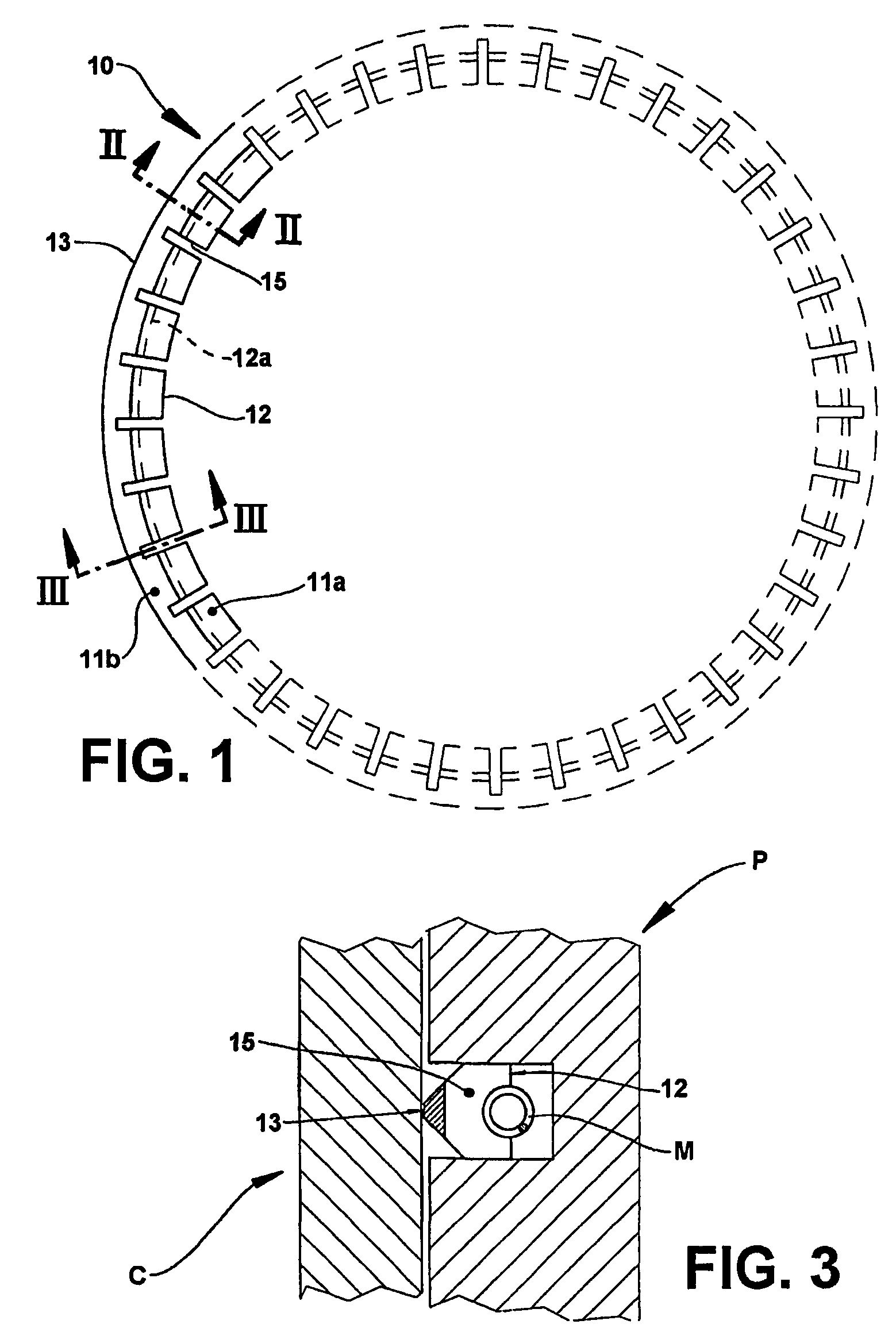
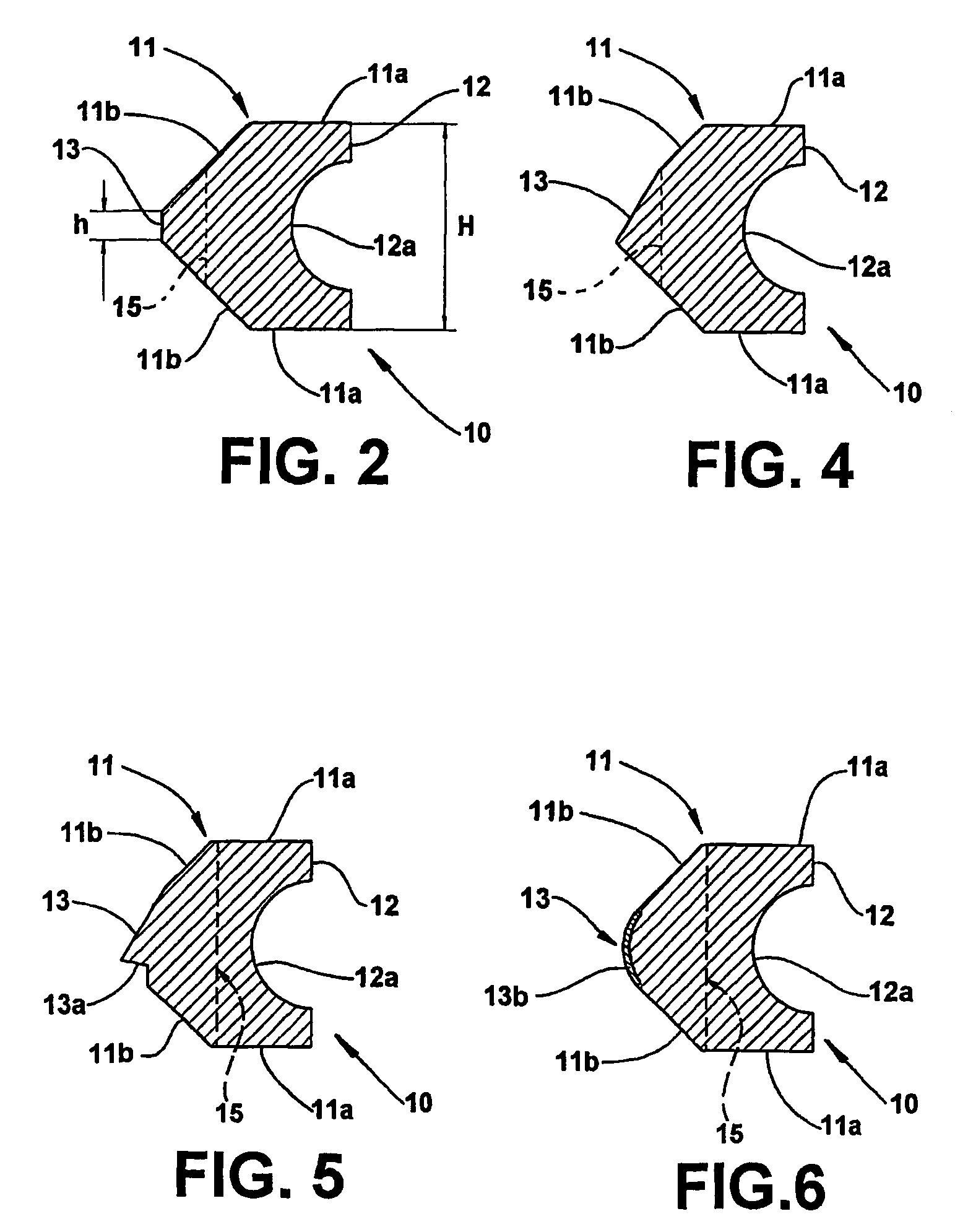
[0044]As known, the annular body has opposite lateral faces, an internal face, defining a support onto which will be seated a resilient expander generally in the form of a metallic spring, and an external contact face to be seated against the internal face of the cylinder. According to the invention, the external contact face is defined by a single continuous surface extension of the annular body presenting, in the axial direction, a height that is substantially smaller than the height of the internal face, each lateral face being defined by at least one lateral face portion that is designed to reduce the moment of inertia of the annular body towards its axis and its center of mass.
[0045]The construction proposed by the invention not only allows for the reduction of the total height of the ring, as it uses only one external contact face, but also the reduction of friction, by reducing the tangential load, without causing damages to the specific pressure that is required for a desired scraping efficiency, since the contact face is conveniently correspondingly reduced.

Problems solved by technology

Nevertheless, the known prior art technology has limitations as to the optimization of friction losses and oil consumption.
It has been found that nearly 25% of friction losses of an engine are due to the rings, and 70% of said losses come from the oil ring under operation, mainly due to its high tangential load.
Experiments and literature show that the lower the specific pressure the higher will be the oil consumption.

Method used


Image

  • Oil ring for an internal combustion engine
  • Oil ring for an internal combustion engine
  • Oil ring for an internal combustion engine

Examples


Embodiment Construction

[0053]As illustrated, the oil ring object of the present invention is made of steel, cast iron, another metal alloy, polymeric material or any other suitable material, comprising an annular body 10 to be mounted to a respective groove of a piston P designed to reciprocate inside a cylinder C of the internal combustion engine.

[0054]The annular body 10 has a pair of end faces 11, which are opposite and generally parallel to each other and orthogonal to the axial axis of the ring, an internal face 12, and an external contact face 13 to be seated against the internal face of the cylinder C, in order to scrape the lubricant oil that is conducted to this region upon operation of the engine. The internal face 12 of the annular body 10 defines a support, generally in the form of a groove 12a, for example having a “V” or “U” profile or combinations of these shapes, onto which will be seated a resilient expander “M” generally defined by a metallic spring that is dimensioned to exert a determi...


PUM


Abstract

An oil ring for an internal combustion engine, comprising a metallic annular body (10) to be mounted around a piston (P) reciprocating inside a cylinder (C) of the engine, said annular body (10) having opposite lateral faces (11), an internal face (12) onto which will be seated a resilient expander (M), and an external contact face (13) to be seated against the internal face of the cylinder (C) and having a height (h) that is substantially smaller than the height (H) of the internal face (12). Each lateral face (11) is defined by one or more lateral face portions (11a, 11b), which are designed to reduce the moment of inertia of the annular body (10), giving higher conformability to the latter. Preferentially, but not exclusively, the annular body (10) can be further provided with channels (15, 16), extended along at least part of the ring hight and which are radially spaced back in relation to the external contact face (13).

Description

[0001]This is a U.S. national phase application under 35 U.S.C. § 371 of International Patent Application No. PCT / BR2002 / 000076, filed May 29, 2002 which claims the benefit of Brazilian Application No. PI 0102824-3, filed May 30, 2001 and Brazilian Application No. PI 0202271-0, filed May 27, 2002. The International Application was published on Dec. 5, 2002 as International Publication No. WO / 2002 / 097310 under PCT Article 21(2) the content of all the applications are incorporated herein in their entirety.FIELD OF THE INVENTION[0002]The present invention refers to an oil flow control ring for the piston of internal combustion engines, said ring having optimized specific pressure and high conformability.BACKGROUND OF THE INVENTION[0003]Until the 1920's, practically all the internal combustion engines used only compression rings. Engine rotations were low and the compression rings were sufficient to control the small amounts of oil sent by the connecting rods to the cylinder walls.[0004...

Claims


Application Information

Patent Timeline
IPC IPC(8): F16J9/12F02F5/00F16J9/06F16J9/20F16J9/26
CPCF16J9/061F16J9/062F16J9/20
Inventor PANELLI, RENATOFERRARESE, ANDRE
Owner MAHLE COMPONENTS DE MOTORES DO BRASIL
Learn More