Coaxial cable connector with replaceable compression ring

a technology of compression ring and coaxial cable, which is applied in the direction of coupling device connection, two-part coupling device, electrical apparatus, etc., can solve the problems of connector loosening, connector loosening, and all have inherent limitations

a technology of compression ring and coaxial cable, which is applied in the direction of coupling device connection, two-part coupling device, electrical apparatus, etc., can solve the problems of connector loosening, connector loosening, and all have inherent limitations

US7252546B1Active Publication Date: 2007-08-07HOLLAND ELECTRONICS

Image

  • Coaxial cable connector with replaceable compression ring
  • Coaxial cable connector with replaceable compression ring
  • Coaxial cable connector with replaceable compression ring

Examples


Embodiment Construction

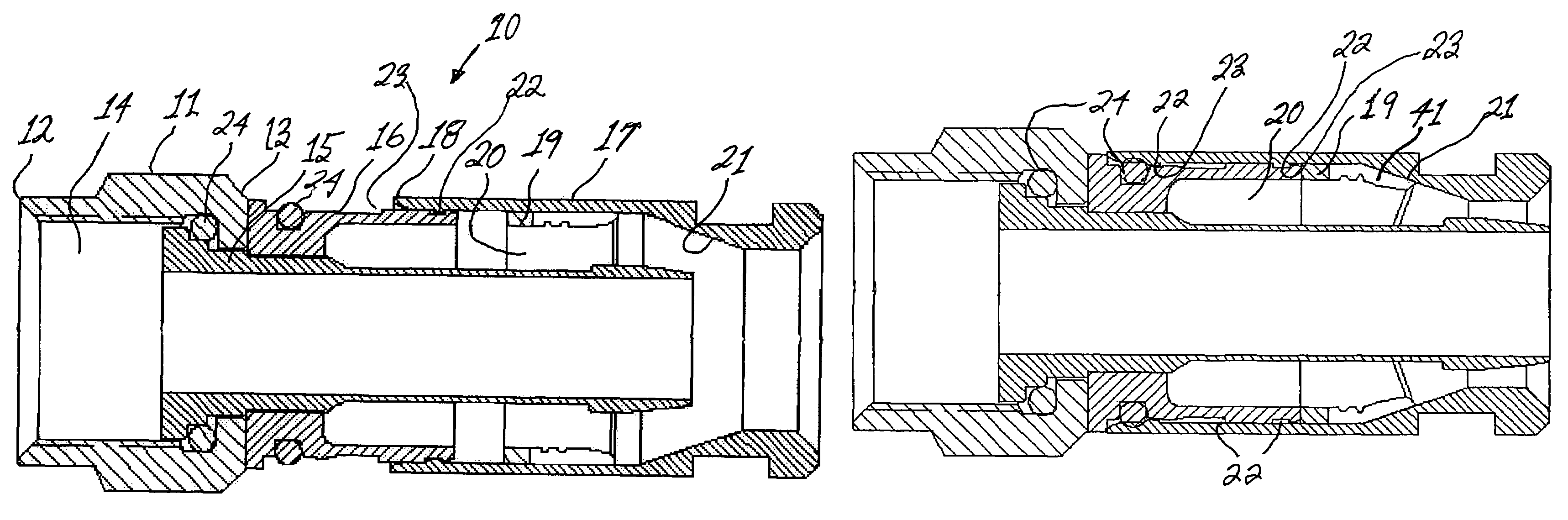
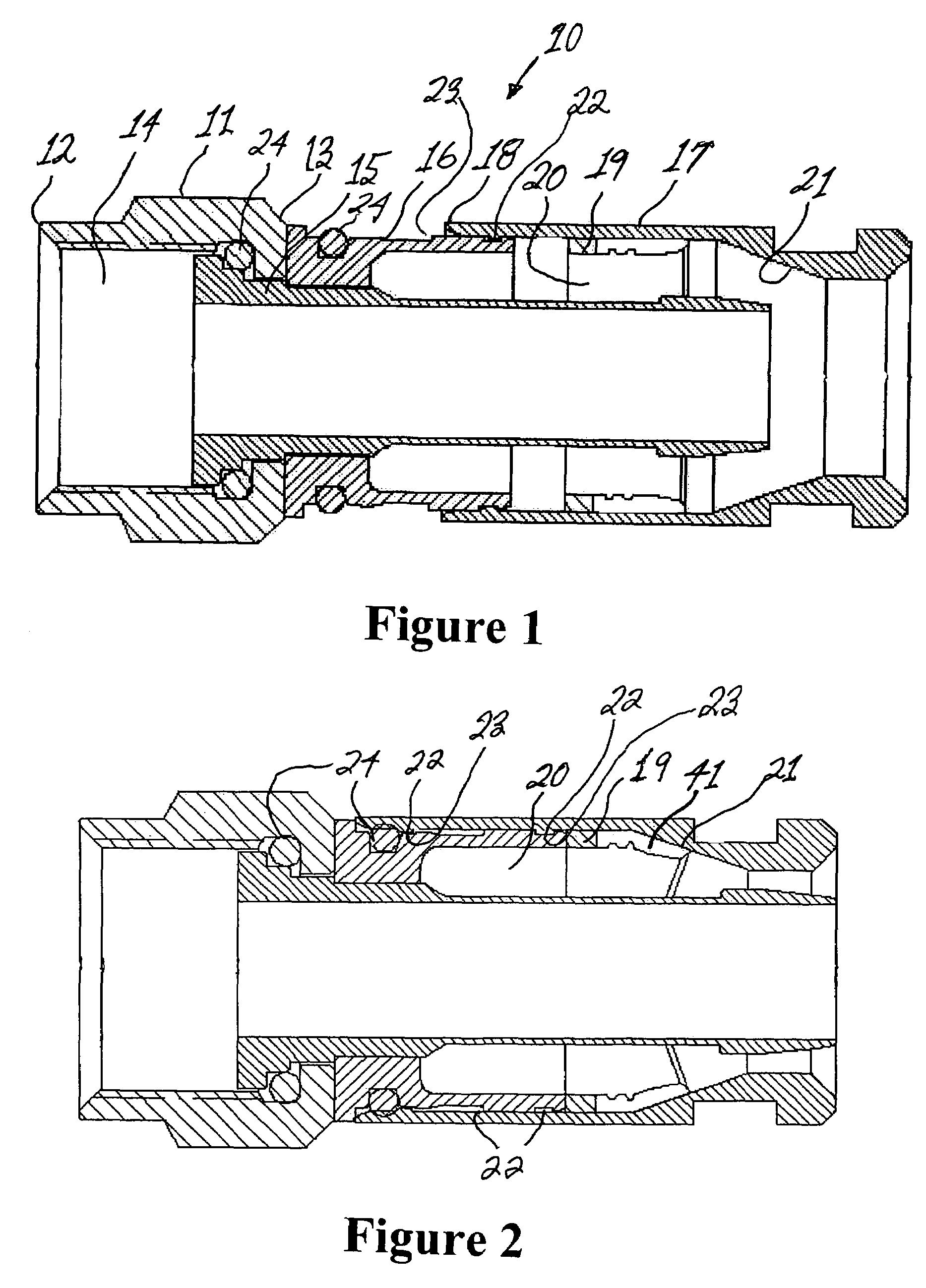
[0020]Prior to attaching a coaxial cable to a male connector, the end of the cable that will be receiving the connector must first be prepared. It will be understood by the artisan that the preparation of the end of the cable will be in accordance with the type of male coaxial cable connector that the cable will be attached (i.e., F-type, BNC, RCA, etc.) as discussed in U.S. Pat. No. 7,008,263, the content and teaching of the patent being incorporated herein by reference thereto. In order to prepare the end of a coaxial cable to receive a male connector, a cutting tool is used by an installer to expose a portion of the central conductor, a length of the dielectric core and a conductive (grounding) braid. The respective lengths of each of the elements comprising the coaxial cable that are exposed by the cutting tool will depend on the particular type of male connector to be attached thereto and are in accordance with industry standards. Following exposure of the conductive braid, the...


PUM


Abstract

A male compression-type coaxial cable connector having an adapter nut attached to a leading end of a tubular connector body portion. The connector body portion has a first axial conduit with a barbed ferrule coaxially mounted therein. The connector further comprises a compression sleeve having a second axial conduit slidingly disposed over a trailing end of the tubular connector body portion. A deformable compression ring is removably disposed within the second axial conduit. In use, the prepared end of the coaxial cable is inserted through the compression sleeve and compression ring and advanced into the connector body conduit until it can be advanced no further. Subsequent advancement of the compression sleeve over the connector body portion, with the assistance of a compression tool, forces the deformable trailing end of the compression ring radially inward to compress the cable jacket and braid thereby providing secure attachment of the connector to the cable. The compression ring is removable and can be replaced with another compression ring having a different inner diameter to accommodate a variety of coaxial cables. The construction permits the compression sleeve to be easily removed for replacing the compression ring and easily reinstalled over the connector body after ring replacement.

Description

BACKGROUND OF THE INVENTION[0001]1. Field of the Invention[0002]The present invention relates to male coaxial cable connectors operable for electrically connecting a center conductor in a coaxial cable to a mating female port.[0003]2. Prior Art[0004]Connectors adapted to form a secure, electrically conductive connection between a coaxial cable and a threaded female port have are well known in the art. Such prior art connectors are discussed, for example, in U.S. Pat. No. 6,217,383 to Holland et al., U.S. Pat. Nos. 6,676,446, 6,153,830 and 6,558,194 to Montena, U.S. Pat. No. 5,024,605 to Ming-Hua, U.S. Pat. No. 4,280,749 to Hemmer, U.S. Pat. No. 4,593,964 to Forney, Jr. et al., U.S. Pat. No. 5,007,861 to Stirling, U.S. Pat. No. 5,073,129 to Szegda, U.S. Pat. No. 3,710,005 to French and U.S. Pat. No. 5,651,699 to Holliday. U.S. Pat. No. 5,879,191 to Burris, discusses prior art efforts to provide a coaxial connector which is moisture-proof and minimizes radiative loss of signal from th...

Claims


Application Information

Patent Timeline
07 Aug 2007
Publication
US7252546B1
IPC
H01R9/05
CPC
H01R9/0524; H01R24/40; H01R2103/00
Inventors
HOLLAND, MICHAEL