Microscope with extended field of vision

a microscope and extended field of vision technology, applied in the field of microscopes, can solve the problems of high magnification, reducing the size of the field of view, and many micro-assembly or micro-manipulation tasks that require micron to sub-micron precision over millimeter work volume, and achieve the effect of high resolution

Active Publication Date: 2007-08-07
RENESSELAER POLYTECHNIC INST
View PDF12 Cites 45 Cited by
  • Summary
  • Abstract
  • Description
  • Claims
  • Application Information

AI Technical Summary

Benefits of technology

[0014]It is another object of the present invention to provide a mosaic image with a high resolution that is free of blurring or aberrations.

Problems solved by technology

However, conventional microscopes suffer from the limitation that high magnification reduces the size of the field of view, which is the maximum object size which may be imaged by a lens.
As a result, many micro-assembly or micro-manipulation tasks that require micron to sub-micron precision over millimeter work volume are beyond the capability of fixed optical microscopes.
This is especially problematic where the biological cell at the second zone of interest is moving.
However, high resolution sensors that can work on a large scale are usually expensive and volume-consuming.
However, the working volume will be limited to the size of the picture itself which is a problem if accuracy is required.
If the robot has to perform a task like a pick-and-place manipulation this volume may not be large enough.
The whole assembly setup might have to be moved under the microscope which may be a problem if delicate assembly is required.
The bandwidth of the motion is limited by the inertia of the platform or microscope, and the vibration resulting from the motion can blur the image or even modify the scene.
However, no high-speed scanning or capture devices are included.

Method used


Image

  • Microscope with extended field of vision
  • Microscope with extended field of vision
  • Microscope with extended field of vision

Examples


Embodiment Construction

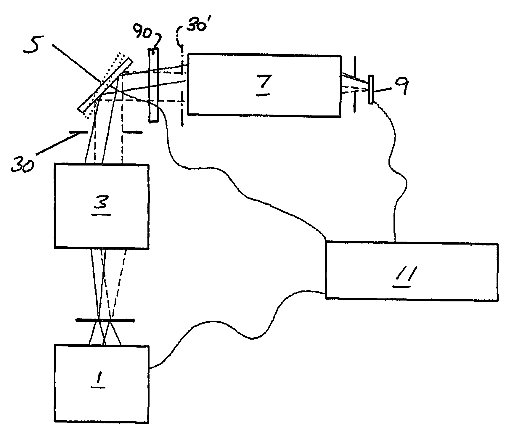
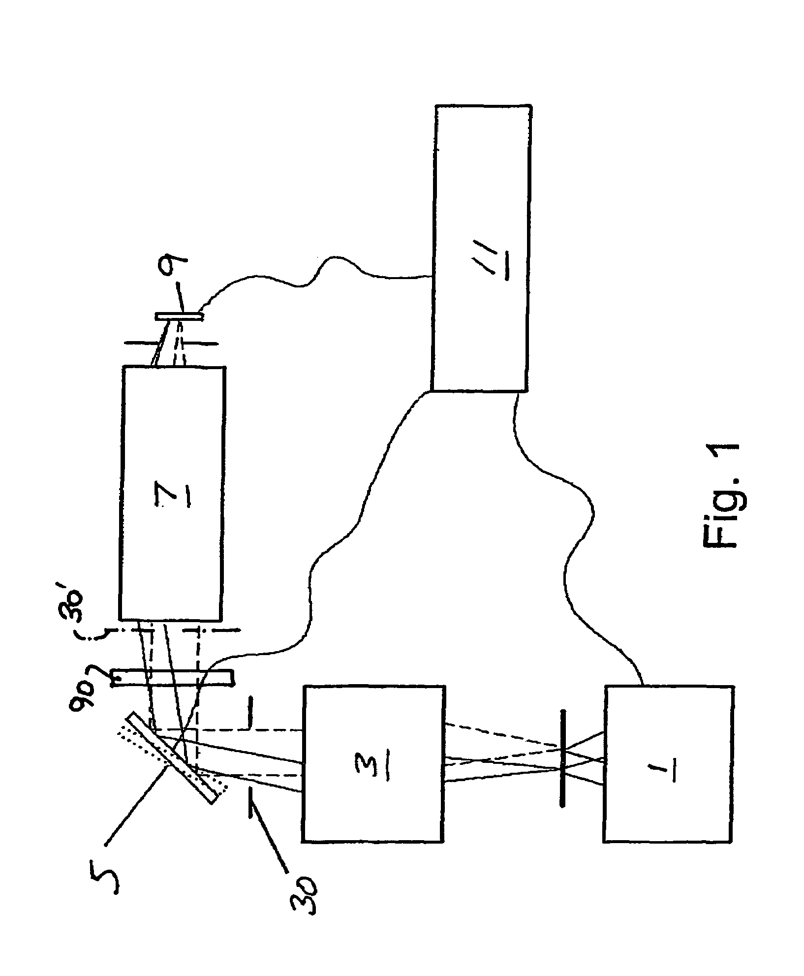
[0026]Referring now to the drawings, in which like reference numerals are used to refer to the same or similar elements, FIG. 1 shows an optical system.

[0027]The optical system can be divided into six elements. The first element is an illumination system 1. A specimen can be illuminated from the bottom due to a dedicated illumination system. It can also be illuminated from the top due to a light beam injected into the optical path. Another possibility is side illumination using fiber bundles for instance.

[0028]The second element is an objective lens assembly 3 that consists of one or more lenses. An object is placed at the focal plane of the lens assembly such that each ray emitting off the same point on the object exit parallel to each other from the lens assembly. One or more lenses in the assembly can be moving to achieve a specific function like focusing or aberration compensation.

[0029]An iris 30 is placed just after the lens assembly to enhance image contrast. Other features l...


PUM


Abstract

An optical system is provided for creating a mosaic image of a large field of view through a microscope at fast refresh rates of about 25 Hz with a high resolution that is free of blurring or aberrations. The optical system includes an objective lens assembly (20), an iris (30), one or more scanning mirrors (40) for high-speed scanning, one or more imaging lenses and irises (50, 60, 80), and a high-speed imaging device (70) arranged in that order from an object. The optical system also includes a mechanism for processing and constructing scanned and captured images into a mosaic image.

Description

FIELD AND BACKGROUND OF THE INVENTION[0001]The present invention relates generally to the field of microscopy and in particular to a new and useful apparatus and method for high-speed image scanning, image capturing, and mosaicking to enlarge the field of view with respect to microscopic objects.[0002]A microscope is an indispensable tool for micro-assembly and micro-manipulation. However, conventional microscopes suffer from the limitation that high magnification reduces the size of the field of view, which is the maximum object size which may be imaged by a lens. As a result, many micro-assembly or micro-manipulation tasks that require micron to sub-micron precision over millimeter work volume are beyond the capability of fixed optical microscopes.[0003]For example, in vitro fertilization requires the manipulation of two microscopic biological cells, a spermatazoid and an ovule. The two biological cells may be separately located in two different zones of interest on a biological p...

Claims


Application Information

Patent Timeline
Patent Type & Authority Patents(United States)
IPC IPC(8): G02B21/00G02B21/36
CPCG02B21/002G02B21/36G02B21/367
Inventor BELLOUARD, YVESPOTSAID, BENJAMIN MICHAELWEN, JOHN T.
Owner RENESSELAER POLYTECHNIC INST
Why Eureka
Try Eureka