Transparent, look-up-free packet forwarding method for optimizing global network throughput based on real-time route status

a packet forwarding and real-time routing technology, applied in the field of packet forwarding schemes in digital communications networks, can solve the problems of not being able to configure more than a single egress port, certain serious limitations of the current packet-switching technique, and the process is known to be rather complex, so as to achieve high-throughput packet-switched networking, efficient multicasting, and fast protection re-routing.

Active Publication Date: 2007-08-07
XENOGENIC DEV LLC
View PDF9 Cites 153 Cited by
  • Summary
  • Abstract
  • Description
  • Claims
  • Application Information

AI Technical Summary

Benefits of technology

[0023]The present invention provides a substantially simpler packet forwarding method that achieves a significantly better performance than the current packet forwarding techniques for delivering packet traffic across administrative domains of networks, as well as between different administrative domains. In particular, the invented packet forwarding method enables novel flexible and dynamic packet multicasting and anycasting, traffic load balancing and route optimization, and fast and efficient packet-level traffic protection re-routing. The invented packet forwarding method can be implemented as a downward-compatible enhancement to packet forwarding standards such as MPLS.
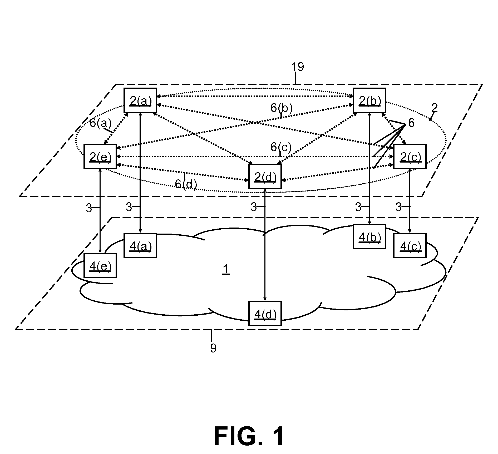
[0024]The invented packet forwarding method provides a way for Layer-N (N=2, 3 or above in the ISO OSI model) packet routing or switching nodes, called upper-layer nodes, to efficiently exchange traffic over a packet-layer protocol transparent packet-switching network domain. The method allows the upper-layer nodes to exchange packet traffic over a single statistically multiplexed point-to-point link per node, and to specify a set of primary and alternative next-hop destination upper-layer nodes per each packet by inserting a simple forwarding instruction tag (FIT) in the header of each packet. In summary, the novel FIT format of the present invention allows an upper-layer node to specify using a simple bit vector, called a Forwarding Enable Vector (FEV), to which ones of the next-hop upper-layer nodes reachable by the transparent network that network should deliver the packet; generally the network will deliver a packet to each such next-hop upper-layer destination node whose associated bit in the FEV of the packet was set to the active state. Such novel, brief form of FIT can be mapped e.g. to the MPLS or link layer headers of the packets, so that the transparent network domain will deliver each packet to an optimal set of the indicated upper-layer destinations along optimal routes, based on the FIT and on the real-time network status. The network status info considered by the transparent network when forwarding a packet includes the reachability of the next-hop upper-layer destinations indicated by the FIT and the current capacity available on alternative routes to those upper-layer nodes.
[0025]In brief, the present invention provides a method for existing upper-layer nodes, such as IP or MPLS routers, to exchange packets over a transparent packet-switching network simply by inserting a flexible and efficient forwarding instruction directly into the header of each packet, based on which, and on the network status, that transparent network delivers the packets. Thereby, the packet forwarding method of the present invention enables to eliminate the step of conventional packet-forwarding methods of having to look-up the forwarding instruction from a route information database for each packet based on the header of the packet. I.e., a packet-switching network that uses the forwarding method of the present invention reads the forwarding instruction for each packet directly from the packet header, instead of searching the forwarding instruction from a separate route table. Furthermore, the forwarding instruction format of the present invention enables efficient multicasting, dynamic load-balancing, fast protection re-routing, as well as scalable, high-throughput packet-switched networking overall.

Problems solved by technology

Naturally, such switching-tables need to be configured and maintained in order for the network to work properly, which process is known to be rather complex especially for networks with a large number of packet-switching nodes.
However, even with their increasing complexity, there are certain serious limitations with the current packet-switching techniques, particularly in the areas of multicasting, anycasting and traffic protection.
While this process requires configuring and maintaining a switching-table containing forwarding instructions per each destination identifier for each packet-switching node in the network, and even though the packet-switches thus become quite complex, this regular packet-switching method does not allow configuring more than a single egress port and a link identifier in the switching-tables per an ingress link without substantial additional complexity.
Thus, conventional packet-switching is not efficient when a portion of the packets would need to be forwarded to a group of more than one egress ports, or to any suitable egress port out of such defined multi- or anycast group.
This in turn requires either multiplying the complexity of conventional packet-switching to support multicast and anycast, thereby limiting the scalability and reducing the cost-efficiency of the switching technology, or replicating a multicast packet multiple times to be send individually i.e. unicast it to each individual destination.
For anycast type of traffic, e.g. in case that one out of a group of servers should be contacted, this unicast method typically can not dynamically select the least loaded i.e. currently best responding server, resulting in non-balanced server load patterns, and often poor client performance experience.
With conventional packet switching, such protection re-routing protection involves software based reconfiguration of routing, switching and / or forwarding tables of the nodes in the network between the source and the destination of the packet, which causes non-deterministic and often intolerably long traffic protection restoration completion times, especially in the case of multiple route, switch and forwarding table entries that would need to be reconfigured simultaneously or over a short period of time.
However, such features are not supported by conventional packet-switching technologies that are based on unicast model and software-configured switching and routing tables.
The fundamental difficulty in providing deterministic end-to-end QoS and optimized efficiency of network resource utilization is that packet traffic in service provider networks consists of a multitude of non-coordinateable individual variable-bandwidth traffic flows across the networks.
Thus, unless traffic flows are rate controlled, network congestion can occur, resulting in packets getting delayed or lost before reaching their destinations, in which cases the packets must often be retransmitted, thus resulting in a single packet consuming network capacity (air-time) multiple times, thus further worsening the congestion.
Thus there is a gap in the required switch interface data rate capacity and the feasible buffering capacity of the order of ten-to-one, which means that the conventional packet queuing techniques based on electrical data storage on RAMs is significantly limiting the maximum switch port data rates for which any type of QoS and congestion control can be provided.
Additionally, as the largest available electrical data storage capacity can currently only be implemented using discrete off-chip RAM parts, the conventional packet queuing mechanisms result in complicated and costly switch hardware implementation.
However, at a properly engineered network, i.e. a network that it has an adequate amount of capacity to serve its access interfaces and that it has no single-point-of-global-failure, if a congestion occurs it is typically because a momentary demand for capacity on a certain route or link within the network, such as a server port, exceeds its physical capacity, while there at the same time are under-utilized alternative routes or links within the network.
These features, however, are not supported by the current unicast-oriented L3 routing or unicast and connection-oriented L2 switching techniques, which state of affairs thus is currently causing-sub-optimal utilization of network resources for dynamic packet traffic.
Furthermore, even if there was no alternative route to bypass a congested egress port of the network domain, in a properly engineered network, during the congestion on that particular overloaded link, there at the same time are under-utilized links, i.e. network fiber capacity having unused bandwidth.

Method used


Image

  • Transparent, look-up-free packet forwarding method for optimizing global network throughput based on real-time route status
  • Transparent, look-up-free packet forwarding method for optimizing global network throughput based on real-time route status
  • Transparent, look-up-free packet forwarding method for optimizing global network throughput based on real-time route status

Examples


Embodiment Construction

[0035]The invention is described herein first by illustrating the novel concepts via a more detailed discussion of the drawings, and then by providing specifications for a currently preferred embodiment of the invention.

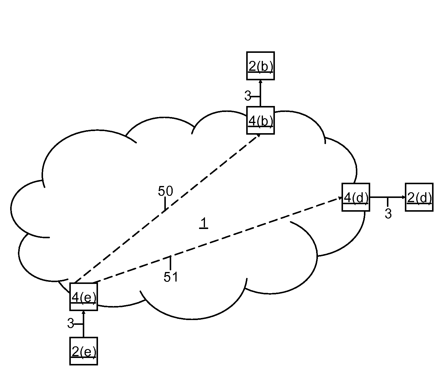
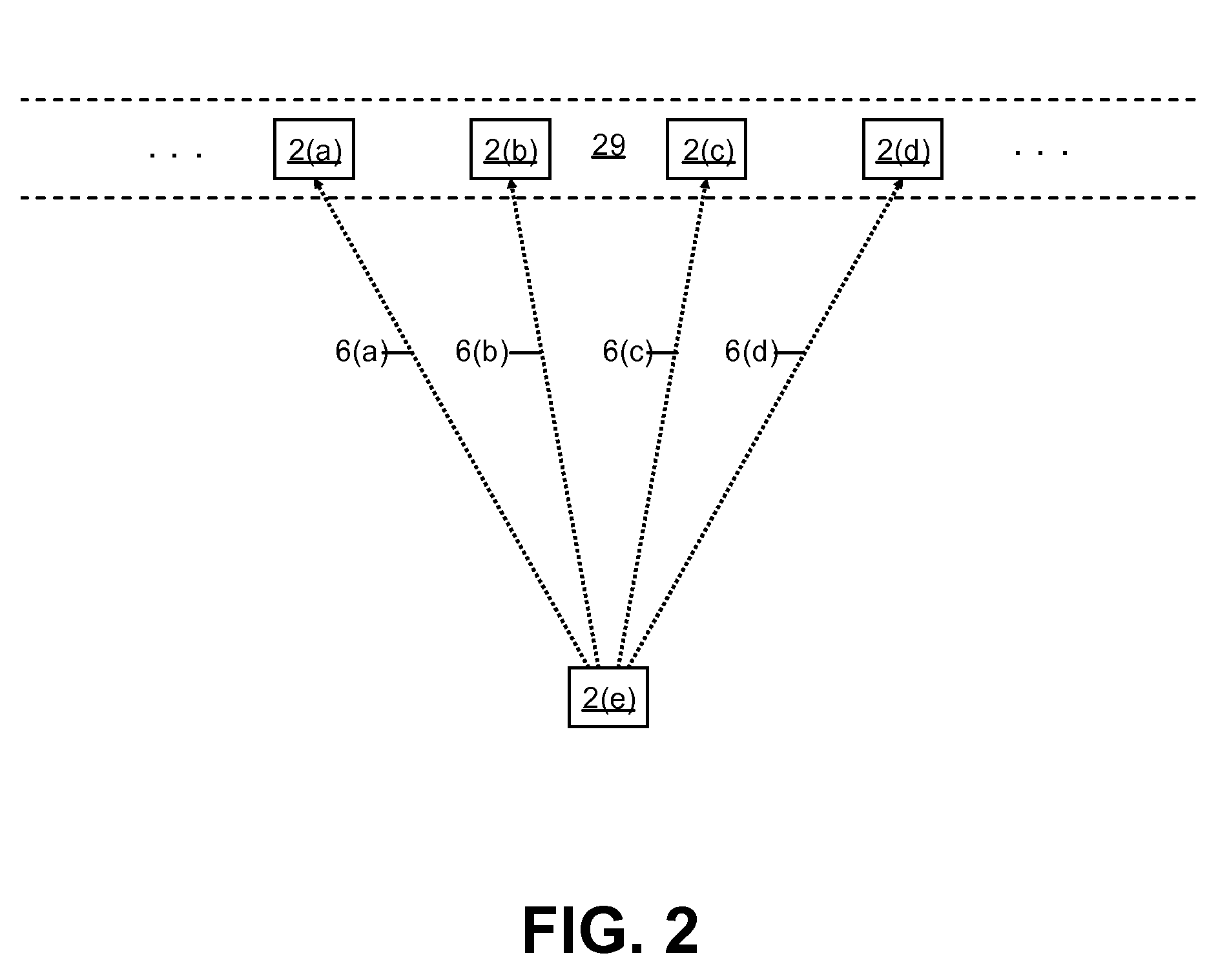
[0036]Symbols and notations used in the drawings:[0037]Solid arrows indicate a communications signal i.e. data traffic flow. Dotted arrows between network elements (drawn as boxes) indicate direct i.e. transparent connectivity at the packet-layer. Gapped arrows indicate a route of a traffic flow across network.[0038]Boxes represent network elements, such as a packet-switch nodes.[0039]Cloud shapes, such as the one below the packet-switches 2 in FIG. 1, present an abstraction of a physical network interconnecting the nodes (4 in FIG. 1) on its edges.[0040]Circular, dotted-line, shapes mark a border of a group of drawn elements that form a logical entity, such as the set 2 of packet-switching nodes, elements 2(a) through 2(e), on the upper network layer 19, in FIG. 1, ...


PUM


Abstract

A packet forwarding method for optimizing packet traffic flow across communications networks and simplifying network management. The invention provides look-up-free and packet-layer-protocol transparent forwarding of multi-protocol packet traffic among Layer-N (N=2 or upper in the ISO OSI model) nodes. The invention enables flexible and efficient packet multicast and anycast capabilities along with real-time dynamic load balancing and fast packet-level traffic protection rerouting. Applications include fast and efficient packet traffic forwarding across administrative domains of Internet, such as an ISP's backbone or an enterprise virtual private network, as well as passing packet traffic over a neutral Internet exchange facility between different administrative domains.

Description

CROSS-REFERENCES TO RELATED APPLICATIONSThe subject matter of this application is related to and makes references to the following patent applications:[0001][1] Co-pending U.S. utility patent application Ser. No. 09 / 938,014, filing date Aug. 24, 2001, by Mark Henrik Sandstrom, entitled “A System and Method for Maximizing the Traffic Delivery Capacity of Packet Transport Networks via Real-time Traffic Pattern Based Optimization of Transport Capacity Allocation”.[0002][2] U.S. Provisional patent application Ser. No. 60 / 356,503, filing date Feb. 11, 2002, by Mark Henrik Sandstrom, entitled “Real-time Control-Plane for Maximizing Billable-Traffic-Throughput of Packet Transport Networks”.This application further claims the benefit under 35 U.S.C. § 119(e) of U.S. Provisional Application No. 60 / 356,503, filed Feb. 11, 2002, which is herein incorporated in its entirety by reference.BACKGROUND OF THE INVENTION[0003]1. Technical Field[0004]The present invention pertains to the field of commu...

Claims


Application Information

Patent Timeline
Patent Type & Authority Patents(United States)
IPC IPC(8): H04L12/28H04L12/56H04L29/08
CPCH04L45/00H04L45/16H04L45/22H04L45/24H04L45/50H04L69/32H04L69/325
Inventor SANDSTROM, MARK HENRIK
Owner XENOGENIC DEV LLC
Why Eureka
Try Eureka